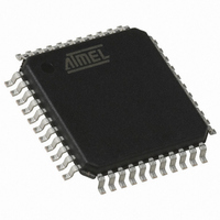
AT89C51IC2-RLTIL Atmel, AT89C51IC2-RLTIL Datasheet - Page 18

AT89C51IC2-RLTIL
Manufacturer Part Number
AT89C51IC2-RLTIL
Description
IC 8051 MCU FLASH 32K 44VQFP
Manufacturer
Atmel
Series
89Cr
Datasheet
1.AT89C51IC2-SLRIM.pdf
(147 pages)
Specifications of AT89C51IC2-RLTIL
Core Processor
8051
Core Size
8-Bit
Speed
40MHz
Connectivity
I²C, SPI, UART/USART
Peripherals
POR, PWM, WDT
Number Of I /o
34
Program Memory Size
32KB (32K x 8)
Program Memory Type
FLASH
Ram Size
1.25K x 8
Voltage - Supply (vcc/vdd)
2.7 V ~ 3.6 V
Oscillator Type
External
Operating Temperature
-40°C ~ 85°C
Package / Case
44-TQFP, 44-VQFP
Lead Free Status / RoHS Status
Contains lead / RoHS non-compliant
Eeprom Size
-
Data Converters
-
Available stocks
Company
Part Number
Manufacturer
Quantity
Price
Company:
Part Number:
AT89C51IC2-RLTIL
Manufacturer:
ATMEL
Quantity:
640
Company:
Part Number:
AT89C51IC2-RLTIL
Manufacturer:
ATMEL
Quantity:
4 116
Idle Modes
Power Down Modes
18
AT89C51IC2
•
•
•
•
•
•
•
•
•
•
•
•
•
•
•
•
Table 18. Overview
PCON.1 PCON.0
0
0
0
0
X
X
X
It is always possible to switch dynamically by software from OscA to OscB, and vice
versa by changing CKS bit.
IDLE modes are achieved by using any instruction that writes into PCON.0 bit (IDL)
IDLE modes A and B depend on previous software sequence, prior to writing into
PCON.0 bit:
IDLE MODE A: OscA is running (OscAEn = 1) and selected (CKS = 1)
IDLE MODE B: OscB is running (OscBEn = 1) and selected (CKS = 0)
The unused oscillator OscA or OscB can be stopped by software by clearing
OscAEn or OscBEn respectively.
IDLE mode can be canceled either by Reset, or by activation of any enabled
interruption
In both cases, PCON.0 bit (IDL) is cleared by hardware
Exit from IDLE modes will leave Oscillators control bits (OscEnA, OscEnB, CKS)
unchanged.
POWER DOWN modes are achieved by using any instruction that writes into
PCON.1 bit (PD)
POWER DOWN modes A and B depend on previous software sequence, prior to
writing into PCON.1 bit:
Both OscA and OscB will be stopped.
POWER DOWN mode can be cancelled either by a hardware Reset, an external
interruption, or the keyboard interrupt.
By Reset signal: The CPU will restart according to OSC bit in Hardware Security Bit
(HSB) register.
By INT0 or INT1 interruption, if enabled: (standard behavioral), request on Pads
must be driven low enough to ensure correct restart of the oscillator which was
selected when entering in Power down.
By keyboard Interrupt if enabled: a hardware clear of the PCON.1 flag ensure the
restart of the oscillator which was selected when entering in Power down.
X
X
X
0
0
0
0
OscBEn OscAEn
0
1
1
1
0
X
0
X
1
1
0
1
0
0
CKS
X
1
1
0
0
1
0
NORMAL MODE
A, OscB stopped
NORMAL MODE
A, OscB running
NORMAL MODE
B, OscA stopped
NORMAL MODE
B, OscA running
INVALID
INVALID
INVALID
Selected Mode
Default mode after power-up or
Warm Reset
Default mode after power-up or
Warm Reset + OscB running
OscB running and selected
OscB running and selected +
OscA running
OscA & OscB cannot be stopped
at the same time
OscA must not be stopped, as
used for CPU and peripherals
OscB must not be stopped as
used for CPU and peripherals
Comment
4301D–8051–02/08


