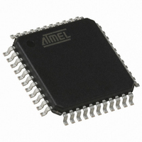
AT89C51IC2-RLTIL Atmel, AT89C51IC2-RLTIL Datasheet - Page 145

AT89C51IC2-RLTIL
Manufacturer Part Number
AT89C51IC2-RLTIL
Description
IC 8051 MCU FLASH 32K 44VQFP
Manufacturer
Atmel
Series
89Cr
Datasheet
1.AT89C51IC2-SLRIM.pdf
(147 pages)
Specifications of AT89C51IC2-RLTIL
Core Processor
8051
Core Size
8-Bit
Speed
40MHz
Connectivity
I²C, SPI, UART/USART
Peripherals
POR, PWM, WDT
Number Of I /o
34
Program Memory Size
32KB (32K x 8)
Program Memory Type
FLASH
Ram Size
1.25K x 8
Voltage - Supply (vcc/vdd)
2.7 V ~ 3.6 V
Oscillator Type
External
Operating Temperature
-40°C ~ 85°C
Package / Case
44-TQFP, 44-VQFP
Lead Free Status / RoHS Status
Contains lead / RoHS non-compliant
Eeprom Size
-
Data Converters
-
Available stocks
Company
Part Number
Manufacturer
Quantity
Price
Company:
Part Number:
AT89C51IC2-RLTIL
Manufacturer:
ATMEL
Quantity:
640
Company:
Part Number:
AT89C51IC2-RLTIL
Manufacturer:
ATMEL
Quantity:
4 116
4301D–8051–02/08
Power Management ............................................................................ 67
Serial Port Interface (SPI) ................................................................... 71
Keyboard Interface ............................................................................. 80
2-wire Interface (TWI) ......................................................................... 84
Hardware Watchdog Timer .............................................................. 102
Power-off Flag ................................................................................... 104
ONCE(TM) Mode (ON Chip Emulation) ........................................... 105
Reduced EMI Mode ........................................................................... 106
Flash EEPROM Memory ................................................................... 107
Electrical Characteristics ................................................................. 128
Interrupt Sources and Vector Addresses............................................................ 66
Reset .................................................................................................................. 67
Reset Recommendation to Prevent Flash Corruption ........................................ 69
Idle Mode ............................................................................................................ 69
Power-down Mode.............................................................................................. 69
Features.............................................................................................................. 71
Signal Description............................................................................................... 71
Functional Description ........................................................................................ 73
Registers............................................................................................................. 81
Description.......................................................................................................... 86
Notes .................................................................................................................. 89
Registers............................................................................................................. 99
Using the WDT ................................................................................................. 102
WDT During Power Down and Idle................................................................... 103
Features............................................................................................................ 107
Flash Programming and Erasure...................................................................... 107
Flash Registers and Memory Map.................................................................... 108
Flash Memory Status........................................................................................ 111
Memory Organization ....................................................................................... 111
Bootloader Architecture .................................................................................... 112
ISP Protocol Description................................................................................... 116
Functional Description ...................................................................................... 117
Flow Description ............................................................................................... 118
API Call Description.......................................................................................... 126
Absolute Maximum Ratings ..............................................................................128
DC Parameters for Standard Voltage ............................................................... 128
ii


