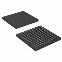
AT91SAM7L128-CU Atmel, AT91SAM7L128-CU Datasheet - Page 494

AT91SAM7L128-CU
Manufacturer Part Number
AT91SAM7L128-CU
Description
MCU ARM7 128K HS FLASH 144-LFBGA
Manufacturer
Atmel
Series
AT91SAMr
Datasheet
1.AT91SAM7L64-CU.pdf
(564 pages)
Specifications of AT91SAM7L128-CU
Core Processor
ARM7
Core Size
16/32-Bit
Speed
36MHz
Connectivity
I²C, SPI, UART/USART
Peripherals
Brown-out Detect/Reset, LCD, POR, PWM, WDT
Number Of I /o
80
Program Memory Size
128KB (128K x 8)
Program Memory Type
FLASH
Ram Size
6K x 8
Voltage - Supply (vcc/vdd)
1.55 V ~ 1.8 V
Data Converters
A/D 4x10b
Oscillator Type
Internal
Operating Temperature
-40°C ~ 85°C
Package / Case
144-LFBGA
Processor Series
AT91SAMx
Core
ARM7TDMI
Data Bus Width
32 bit
Data Ram Size
6 KB
Interface Type
2-Wire, SPI, USART
Maximum Clock Frequency
36 MHz
Number Of Programmable I/os
80
Number Of Timers
3
Maximum Operating Temperature
+ 85 C
Mounting Style
SMD/SMT
3rd Party Development Tools
JTRACE-ARM-2M, MDK-ARM, RL-ARM, ULINK2
Development Tools By Supplier
AT91SAM-ICE, AT91-ISP, AT91SAM7L-EK
Minimum Operating Temperature
- 40 C
On-chip Adc
10 bit, 4 Channel
For Use With
AT91SAM7L-STK - KIT EVAL FOR AT91SAM7LAT91SAM-ICE - EMULATOR FOR AT91 ARM7/ARM9
Lead Free Status / RoHS Status
Lead free / RoHS Compliant
Eeprom Size
-
Lead Free Status / Rohs Status
Details
Available stocks
Company
Part Number
Manufacturer
Quantity
Price
Company:
Part Number:
AT91SAM7L128-CU
Manufacturer:
Atmel
Quantity:
2 660
- Current page: 494 of 564
- Download datasheet (9Mb)
34.5
494
Functional Description
AT91SAM7L128/64 Preliminary
After the initialization sequence the SLCDCC is ready to be enabled in order to enter the display
phase (where it is possible to do more than display data written in the SLCDC memory) up to the
disable sequence.
There are two ways to disable the SLCDC
• Initialization Sequence:
1. Select the LCD supply source in the shutdown controller
2. Select the clock division (SLDCD_FRR) to use a proper frame rate
3. Enter the number of common and segments terminals (SLDCD_MR)
4. Select the bias in compliance with the LCD manufacturer data sheet
5. Enter buffer driving time
• During the Display Phase:
1. Data may be written at any time in the SLCDC memory, they are automatically latched
2. It is possible to:
• Disable Sequence:
1. By using the LCDDIS (LCD Disable) bit. (In this case, SLCDC configuration and mem-
2. Or by using the SWRST (Software Reset) bit.
– Internal: The on chip charge pump is selected,
– External: the external supply source has to be between 2 and 3.4 V
and displayed at the next LCD frame
– Adjust contrast
– Adjust the frame frequency
– Adjust buffer driving time
– Reduce the SLCDC consumption by entering in low-power waveform at any time
– Use the large set of display features such as blinking, inverted blink, etc.
ory content are kept.)
6257A–ATARM–20-Feb-08
Related parts for AT91SAM7L128-CU
Image
Part Number
Description
Manufacturer
Datasheet
Request
R

Part Number:
Description:
KIT EVAL FOR AT91SAM7L
Manufacturer:
Atmel
Datasheet:

Part Number:
Description:
DEV KIT FOR AVR/AVR32
Manufacturer:
Atmel
Datasheet:

Part Number:
Description:
INTERVAL AND WIPE/WASH WIPER CONTROL IC WITH DELAY
Manufacturer:
ATMEL Corporation
Datasheet:

Part Number:
Description:
Low-Voltage Voice-Switched IC for Hands-Free Operation
Manufacturer:
ATMEL Corporation
Datasheet:

Part Number:
Description:
MONOLITHIC INTEGRATED FEATUREPHONE CIRCUIT
Manufacturer:
ATMEL Corporation
Datasheet:

Part Number:
Description:
AM-FM Receiver IC U4255BM-M
Manufacturer:
ATMEL Corporation
Datasheet:

Part Number:
Description:
Monolithic Integrated Feature Phone Circuit
Manufacturer:
ATMEL Corporation
Datasheet:

Part Number:
Description:
Multistandard Video-IF and Quasi Parallel Sound Processing
Manufacturer:
ATMEL Corporation
Datasheet:

Part Number:
Description:
High-performance EE PLD
Manufacturer:
ATMEL Corporation
Datasheet:

Part Number:
Description:
8-bit Flash Microcontroller
Manufacturer:
ATMEL Corporation
Datasheet:

Part Number:
Description:
2-Wire Serial EEPROM
Manufacturer:
ATMEL Corporation
Datasheet:


