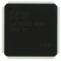
LH79520N0Q000B1;55 NXP Semiconductors, LH79520N0Q000B1;55 Datasheet - Page 28

LH79520N0Q000B1;55
Manufacturer Part Number
LH79520N0Q000B1;55
Description
IC ARM7 BLUESTREAK MCU 176LQFP
Manufacturer
NXP Semiconductors
Series
BlueStreak ; LH7r
Datasheet
1.LH79520N0Q000B155.pdf
(59 pages)
Specifications of LH79520N0Q000B1;55
Package / Case
176-LQFP
Core Processor
ARM7
Core Size
32-Bit
Speed
77.4MHz
Connectivity
EBI/EMI, IrDA, Microwire, SPI, SSI, SSP, UART/USART
Peripherals
DMA, LCD, POR, PWM, WDT
Number Of I /o
64
Program Memory Type
ROMless
Ram Size
32K x 8
Voltage - Supply (vcc/vdd)
1.62 V ~ 3.6 V
Oscillator Type
External
Operating Temperature
-40°C ~ 85°C
Processor Series
LH795
Core
ARM7TDMI-S
Data Bus Width
32 bit
Data Ram Size
32 KB
Interface Type
JTAG, UART
Maximum Clock Frequency
77.4 MHz
Number Of Programmable I/os
64
Number Of Timers
3
Operating Supply Voltage
1.8 V
Maximum Operating Temperature
+ 85 C
Mounting Style
SMD/SMT
3rd Party Development Tools
MDK-ARM, RL-ARM, ULINK2
Minimum Operating Temperature
- 40 C
Lead Free Status / RoHS Status
Lead free / RoHS Compliant
Eeprom Size
-
Program Memory Size
-
Data Converters
-
Lead Free Status / Rohs Status
Lead free / RoHS Compliant
Other names
568-4331
935285044557
LH79520N0Q000B1
935285044557
LH79520N0Q000B1
LH79520
CURRENT CONSUMPTION BY OPERATING MODE
parameters. To make this data more usable, the values
presented in Table 9 were derived under the conditions
presented here.
Maximum Specified Value
determined using these operating characteristics:
• All IP blocks either operating or enabled at maximum
• Core operating at maximum power configuration
• All I/O loads at maximum (50 pF)
• All voltages at maximum specified values
• Maximum specified ambient temperature.
Typical
using a ‘typical’ application under ‘typical’ environmental
conditions and the following operating characteristics:
• SPI, UART, PWMs, and Timer peripherals operat-
• LCD enabled with 320 × 240 × 16-bit color, 60 Hz
• I/O loads at nominal
• Cache enabled
• FCLK = 77.4 MHz; HCLK = 51.6 MHz
• All voltages at typical values
• Nominal case temperature.
PERIPHERAL CURRENT CONSUMPTION
10 shows the typical current consumption for each of
the on-board peripheral blocks. The values were deter-
mined with the peripheral clock running at maximum
frequency, typical conditions, and no I/O loads.
28
frequency and size configuration
ing; all other peripherals disabled
refresh rate
Current consumption can depend on a number of
The values specified in the MAXIMUM column were
The values in the TYPICAL column were determined
In addition to the modal current consumption, Table
Rev. 01 — 16 July 2007
NXP Semiconductors
NOTE: *ICORE = 58 mA MAX., IIO = 19 mA MAX., all active
SYMBOL
ICORE
ICORE
ICORE
ILEAK
ILEAK
ILEAK
IIO
IIO
IIO
Table 10. Peripheral Current Consumption
Counter/Timers
PERIPHERAL
Table 9. Current Consumption by Mode
UARTs
DMA
RTC
SSP
LCD
Core Current
Leakage Current, Core and I/O
Leakage Current, Core and I/O
Core Current
I/O Current
Current drawn by I/O
Core Current
Current drawn by I/O
Leakage Current, Core and I/O
STOP2 MODE (RTC OFF)
STOP2 MODE (RTC ON)
PARAMETER
STANDBY MODE
ACTIVE MODE*
SLEEP MODE
STOP1 MODE
TYPICAL
Preliminary data sheet
200
500
207
4.1
2.2
5
System-on-Chip
TYP. UNITS
33.6
29.6
2.96
9.6
0.8
3.8
35
18
2
UNITS
mA
mA
µA
µA
µA
µA
mA
mA
mA
mA
mA
mA
µA
µA
µA


