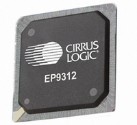
EP9312-IBZ Cirrus Logic Inc, EP9312-IBZ Datasheet - Page 16

EP9312-IBZ
Manufacturer Part Number
EP9312-IBZ
Description
IC ARM920T MCU 200MHZ 352-PBGA
Manufacturer
Cirrus Logic Inc
Series
EP9r
Specifications of EP9312-IBZ
Core Size
16/32-Bit
Package / Case
352-BGA
Core Processor
ARM9
Speed
200MHz
Connectivity
EBI/EMI, EIDE, Ethernet, I²C, IrDA, Keypad/Touchscreen, SPI, UART/USART, USB
Peripherals
AC'97, DMA, I²:S, LCD, LED, MaverickKey, POR, PWM, WDT
Number Of I /o
16
Program Memory Type
ROMless
Ram Size
32K x 8
Voltage - Supply (vcc/vdd)
1.65 V ~ 3.6 V
Data Converters
A/D 8x12b
Oscillator Type
External
Operating Temperature
-40°C ~ 85°C
Controller Family/series
(ARM9)
A/d Converter
12 Bits
No. Of I/o Pins
65
Clock Frequency
200MHz
Processor Series
EP93xx
Core
ARM920T
Data Bus Width
32 bit
3rd Party Development Tools
MDK-ARM, RL-ARM, ULINK2
Lead Free Status / RoHS Status
Lead free / RoHS Compliant
Eeprom Size
-
Program Memory Size
-
Lead Free Status / Rohs Status
Details
Other names
598-1260
Available stocks
Company
Part Number
Manufacturer
Quantity
Price
Company:
Part Number:
EP9312-IBZ
Manufacturer:
CIRRUS
Quantity:
30
Company:
Part Number:
EP9312-IBZ
Manufacturer:
HITTITE
Quantity:
1 200
- Current page: 16 of 824
- Download datasheet (13Mb)
EP93xx User’s Guide
xvi
with SPO=0 and SPH=0 ..............................................................................................................................23-6
with SPO=1 and SPH=0 ..............................................................................................................................23-8
Figure 10-4. Edge-triggered DREQ Mode .................................................................................................10-17
Figure 11-1. USB Focus Areas ...................................................................................................................11-2
Figure 11-2. Communication Channels .......................................................................................................11-3
Figure 11-3. Typical List Structure ..............................................................................................................11-4
Figure 11-4. Interrupt Endpoint Descriptor Structure ..................................................................................11-5
Figure 11-5. Sample Interrupt Endpoint Schedule ......................................................................................11-6
Figure 11-6. USB Host Controller Block Diagram .......................................................................................11-9
Figure 12-1. 32-bit Read, 32-bit Memory, 0 Wait Cycles, RBLE = 1, WAITn Inactive.................................12-3
Figure 12-2. 32-bit Write, 32-bit Memory, 0 Wait Cycles, RBLE = 1, WAITn Inactive.................................12-3
Figure 12-3. 16-bit Read, 16-bit Memory, RBLE = 1, WAITn Active ...........................................................12-4
Figure 12-4. 16-bit Write, 16-bit Memory, RBLE = 1, WAITn Active ...........................................................12-4
Figure 12-5. Single PC Card Interface ........................................................................................................12-7
Figure 14-1. UART Block Diagram ..............................................................................................................14-3
Figure 14-2. UART Character Frame .........................................................................................................14-6
Figure 14-3. UART Character Frame ..........................................................................................................14-6
Figure 15-1. IrDA SIR Encoder/decoder Block Diagram .............................................................................15-2
Figure 15-2. IrDA Data Modulation (3/16) ...................................................................................................15-4
Figure 17-1. RZ1/NRZ Bit Encoding Example.............................................................................................17-9
Figure 17-2. 4PPM Modulation Encoding..................................................................................................17-14
Figure 17-3. 4PPM Modulation Example...................................................................................................17-15
Figure 17-4. IrDA (4.0 Mbps) Transmission Format ..................................................................................17-15
Figure 21-1. Architectural Overview of the I
Figure 21-2. Bit Clock Generation Example ...........................................................................................21-10
Figure 21-3. Frame Format for Right Justified Data ..................................................................................21-10
Figure 23-1. Texas Instruments Synchronous Serial Frame Format (Single Transfer)...............................23-4
Figure 23-2. TI Synchronous Serial Frame Format (Continuous Transfer) .................................................23-4
Figure 23-3. Motorola SPI Frame Format (Single Transfer) with SPO=0 and SPH=0 ................................23-5
Figure 23-4. Motorola SPI Frame Format (Continuous Transfer)
Figure 23-5. Motorola SPI Frame Format with SPO=0 and SPH=1 ............................................................23-7
Figure 23-6. Motorola SPI Frame Format (Single Transfer) with SPO=1 and SPH=0 ................................23-8
Figure 23-7. Motorola SPI Frame Format (Continuous Transfer)
Figure 23-8. Motorola SPI Frame Format with SPO=1 and SPH=1 ............................................................23-9
Figure 23-9. Microwire Frame Format (Single Transfer) ...........................................................................23-10
Figure 23-10. Microwire Frame Format (Continuous Transfers) ...............................................................23-12
Figure 23-11. Microwire Frame Format, SFRMIN Input Setup and Hold Requirements ...........................23-12
Figure 24-1. PWM_INV Example ................................................................................................................24-6
2
©
S Controller ...........................................................................21-1
Copyright 2007 Cirrus Logic, Inc.
DS785UM1
Related parts for EP9312-IBZ
Image
Part Number
Description
Manufacturer
Datasheet
Request
R

Part Number:
Description:
IC ARM9 SOC UNIVERSAL 352PBGA
Manufacturer:
Cirrus Logic Inc
Datasheet:

Part Number:
Description:
System-on-Chip Processor
Manufacturer:
Cirrus Logic Inc
Datasheet:

Part Number:
Description:
IC ARM920T MCU 200MHZ 352-PBGA
Manufacturer:
Cirrus Logic Inc
Datasheet:

Part Number:
Description:
Development Kit
Manufacturer:
Cirrus Logic Inc
Datasheet:

Part Number:
Description:
Development Kit
Manufacturer:
Cirrus Logic Inc
Datasheet:

Part Number:
Description:
High-efficiency PFC + Fluorescent Lamp Driver Reference Design
Manufacturer:
Cirrus Logic Inc
Datasheet:

Part Number:
Description:
Development Kit
Manufacturer:
Cirrus Logic Inc
Datasheet:

Part Number:
Description:
Development Kit
Manufacturer:
Cirrus Logic Inc
Datasheet:

Part Number:
Description:
Development Kit
Manufacturer:
Cirrus Logic Inc
Datasheet:

Part Number:
Description:
Development Kit
Manufacturer:
Cirrus Logic Inc
Datasheet:

Part Number:
Description:
Development Kit
Manufacturer:
Cirrus Logic Inc
Datasheet:

Part Number:
Description:
Development Kit
Manufacturer:
Cirrus Logic Inc
Datasheet:

Part Number:
Description:
Ref Bd For Speakerbar MSA & DSP Products
Manufacturer:
Cirrus Logic Inc


