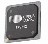
EP9312-IBZ Cirrus Logic Inc, EP9312-IBZ Datasheet - Page 426

EP9312-IBZ
Manufacturer Part Number
EP9312-IBZ
Description
IC ARM920T MCU 200MHZ 352-PBGA
Manufacturer
Cirrus Logic Inc
Series
EP9r
Specifications of EP9312-IBZ
Core Size
16/32-Bit
Package / Case
352-BGA
Core Processor
ARM9
Speed
200MHz
Connectivity
EBI/EMI, EIDE, Ethernet, I²C, IrDA, Keypad/Touchscreen, SPI, UART/USART, USB
Peripherals
AC'97, DMA, I²:S, LCD, LED, MaverickKey, POR, PWM, WDT
Number Of I /o
16
Program Memory Type
ROMless
Ram Size
32K x 8
Voltage - Supply (vcc/vdd)
1.65 V ~ 3.6 V
Data Converters
A/D 8x12b
Oscillator Type
External
Operating Temperature
-40°C ~ 85°C
Controller Family/series
(ARM9)
A/d Converter
12 Bits
No. Of I/o Pins
65
Clock Frequency
200MHz
Processor Series
EP93xx
Core
ARM920T
Data Bus Width
32 bit
3rd Party Development Tools
MDK-ARM, RL-ARM, ULINK2
Lead Free Status / RoHS Status
Lead free / RoHS Compliant
Eeprom Size
-
Program Memory Size
-
Lead Free Status / Rohs Status
Details
Other names
598-1260
Available stocks
Company
Part Number
Manufacturer
Quantity
Price
Company:
Part Number:
EP9312-IBZ
Manufacturer:
CIRRUS
Quantity:
30
Company:
Part Number:
EP9312-IBZ
Manufacturer:
HITTITE
Quantity:
1 200
- Current page: 426 of 824
- Download datasheet (13Mb)
10
10-32
DMA Controller
EP93xx User’s Guide
DoneIntEn:
ENABLE:
START:
BWC:
Copyright 2007 Cirrus Logic
of the source and destination addresses to avoid any
problems in the case where software erroneously
programs a byte-aligned address. The SCT bit is used
only when in M2M software-triggered transfer mode.
Setting this bit to “1” enables the generation of the DONE
Interrupt which indicates if the transfer completed
successfully.
Setting this bit to 1 enables the channel, clearing this bit
disables the channel. The channel must always be
enabled after writing the Source/Destination Base address
registers and the BCR register. When a channel is
disabled, the external peripheral signals will be placed in
their inactive state.
Start Transfer. When this bit is set, the DMA begins M2M
transfer in accordance with the values in the control
registers. START is cleared automatically after one clock
cycle and is always read as a logic 0. This bit, in effect,
provides a “Software-triggered DMA capability”. A channel
must be configured and enabled before setting the START
bit. This bit is not used for external DMA transfers, or for
IDE and SSP transfers. For a double-buffer software
triggered DMA transfer, the START bit need only be set
once, that is, at the very beginning of transfer. It is
sufficient for software to program the ‘other’ buffer
descriptor only, in order to guarantee rollover to the
second buffer when the byte count of the first buffer has
been reached.
Bandwidth Control. These 4 bits are used to indicate the
number of bytes in a block transfer. When the BCR
register value is within 15 bytes of a multiple of the BWC
value, the DMA releases the bus by negating the AHB bus
request strobe allowing lower priority masters to be
granted control of the bus. BWC = 0000 specifies the
maximum transfer rate: other values specify a transfer rate
limit.
The BWC bits should only be set for software triggered
M2M transfers, where HREQ stays asserted throughout
the transfer. For transfer to/from external devices, HREQ
is released after every transfer, and so bandwidth control
is not needed.
The BWC bits are ignored when in external DMA transfer
mode.
DS785UM1
Related parts for EP9312-IBZ
Image
Part Number
Description
Manufacturer
Datasheet
Request
R

Part Number:
Description:
IC ARM9 SOC UNIVERSAL 352PBGA
Manufacturer:
Cirrus Logic Inc
Datasheet:

Part Number:
Description:
System-on-Chip Processor
Manufacturer:
Cirrus Logic Inc
Datasheet:

Part Number:
Description:
IC ARM920T MCU 200MHZ 352-PBGA
Manufacturer:
Cirrus Logic Inc
Datasheet:

Part Number:
Description:
Development Kit
Manufacturer:
Cirrus Logic Inc
Datasheet:

Part Number:
Description:
Development Kit
Manufacturer:
Cirrus Logic Inc
Datasheet:

Part Number:
Description:
High-efficiency PFC + Fluorescent Lamp Driver Reference Design
Manufacturer:
Cirrus Logic Inc
Datasheet:

Part Number:
Description:
Development Kit
Manufacturer:
Cirrus Logic Inc
Datasheet:

Part Number:
Description:
Development Kit
Manufacturer:
Cirrus Logic Inc
Datasheet:

Part Number:
Description:
Development Kit
Manufacturer:
Cirrus Logic Inc
Datasheet:

Part Number:
Description:
Development Kit
Manufacturer:
Cirrus Logic Inc
Datasheet:

Part Number:
Description:
Development Kit
Manufacturer:
Cirrus Logic Inc
Datasheet:

Part Number:
Description:
Development Kit
Manufacturer:
Cirrus Logic Inc
Datasheet:

Part Number:
Description:
Ref Bd For Speakerbar MSA & DSP Products
Manufacturer:
Cirrus Logic Inc


