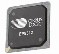
EP9312-IBZ Cirrus Logic Inc, EP9312-IBZ Datasheet - Page 520

EP9312-IBZ
Manufacturer Part Number
EP9312-IBZ
Description
IC ARM920T MCU 200MHZ 352-PBGA
Manufacturer
Cirrus Logic Inc
Series
EP9r
Specifications of EP9312-IBZ
Core Size
16/32-Bit
Package / Case
352-BGA
Core Processor
ARM9
Speed
200MHz
Connectivity
EBI/EMI, EIDE, Ethernet, I²C, IrDA, Keypad/Touchscreen, SPI, UART/USART, USB
Peripherals
AC'97, DMA, I²:S, LCD, LED, MaverickKey, POR, PWM, WDT
Number Of I /o
16
Program Memory Type
ROMless
Ram Size
32K x 8
Voltage - Supply (vcc/vdd)
1.65 V ~ 3.6 V
Data Converters
A/D 8x12b
Oscillator Type
External
Operating Temperature
-40°C ~ 85°C
Controller Family/series
(ARM9)
A/d Converter
12 Bits
No. Of I/o Pins
65
Clock Frequency
200MHz
Processor Series
EP93xx
Core
ARM920T
Data Bus Width
32 bit
3rd Party Development Tools
MDK-ARM, RL-ARM, ULINK2
Lead Free Status / RoHS Status
Lead free / RoHS Compliant
Eeprom Size
-
Program Memory Size
-
Lead Free Status / Rohs Status
Details
Other names
598-1260
Available stocks
Company
Part Number
Manufacturer
Quantity
Price
Company:
Part Number:
EP9312-IBZ
Manufacturer:
CIRRUS
Quantity:
30
Company:
Part Number:
EP9312-IBZ
Manufacturer:
HITTITE
Quantity:
1 200
- Current page: 520 of 824
- Download datasheet (13Mb)
13
13-24
SDRAM, SyncROM, and SyncFLASH Controller
EP93xx User’s Guide
SFConfigAddr:
2KPAGE:
CasLat:
Copyright 2007 Cirrus Logic
When writing to a SyncFLASH device, only single writes
(burst-of-one) are allowed. The value that is written to this
bit specifies that a burst length of either one or four will be
used for Write accesses:
0 - Burst-of-four accesses for both Reads and Writes
1 - Burst-of-one accesses for Writes (SyncFLASH support)
and burst-of-four accesses for Reads
When WBM = ‘1’, the Synchronous Memory controller will
not issue refresh cycles to this domain.
A single word write occurs when the ARM assembly
instruction, ‘str’, is executed. Writing WBM = ‘1’ will not
prevent burst-of-four writes from occurring when the ARM
assembly instruction, ‘stm’, is executed. So, only use
ARM assembly “str” instructions for Write accesses
to SyncFLASH devices.
Synchronous memory CAS Latency - Read/Write
The value written to this field specifies the CAS latency
that the Synchronous Memory controller uses for Read or
Write accesses to SDRAM or SyncROM devices:
000 - Reserved
001 - CAS Latency = 2
010 - CAS Latency = 3 (also normal default)
011 - CAS Latency =4
100 - CAS Latency =5 (also default when booting from a
SyncROM device)
101 - CAS Latency =6
110 - CAS Latency = 7
111 - CAS Latency =8
SyncFLASH Configuration register read - Read/Write
The value written to this bit specifies either normal
operation or that the Synchronous Memory controller is
caused to perform a Read access to the Configuration
register that is inside a SyncFLASH device:
0 - Normal operation
1 - Read SyncFLASH Configuration register
The AutoPrecharge bit must be ‘0’ before the
SFConfigAddr bit is written to ‘1’.
Synchronous memory 2K byte Page - Read/Write
DS785UM1
Related parts for EP9312-IBZ
Image
Part Number
Description
Manufacturer
Datasheet
Request
R

Part Number:
Description:
IC ARM9 SOC UNIVERSAL 352PBGA
Manufacturer:
Cirrus Logic Inc
Datasheet:

Part Number:
Description:
System-on-Chip Processor
Manufacturer:
Cirrus Logic Inc
Datasheet:

Part Number:
Description:
IC ARM920T MCU 200MHZ 352-PBGA
Manufacturer:
Cirrus Logic Inc
Datasheet:

Part Number:
Description:
Development Kit
Manufacturer:
Cirrus Logic Inc
Datasheet:

Part Number:
Description:
Development Kit
Manufacturer:
Cirrus Logic Inc
Datasheet:

Part Number:
Description:
High-efficiency PFC + Fluorescent Lamp Driver Reference Design
Manufacturer:
Cirrus Logic Inc
Datasheet:

Part Number:
Description:
Development Kit
Manufacturer:
Cirrus Logic Inc
Datasheet:

Part Number:
Description:
Development Kit
Manufacturer:
Cirrus Logic Inc
Datasheet:

Part Number:
Description:
Development Kit
Manufacturer:
Cirrus Logic Inc
Datasheet:

Part Number:
Description:
Development Kit
Manufacturer:
Cirrus Logic Inc
Datasheet:

Part Number:
Description:
Development Kit
Manufacturer:
Cirrus Logic Inc
Datasheet:

Part Number:
Description:
Development Kit
Manufacturer:
Cirrus Logic Inc
Datasheet:

Part Number:
Description:
Ref Bd For Speakerbar MSA & DSP Products
Manufacturer:
Cirrus Logic Inc


