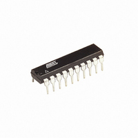
ATTINY26L-8PU Atmel, ATTINY26L-8PU Datasheet - Page 124

ATTINY26L-8PU
Manufacturer Part Number
ATTINY26L-8PU
Description
IC MCU AVR 2K 5V 8MHZ 20-DIP
Manufacturer
Atmel
Series
AVR® ATtinyr
Datasheets
1.ATTINY26-16MC.pdf
(18 pages)
2.ATTINY26-16MC.pdf
(182 pages)
3.ATTINY26L-8PU.pdf
(183 pages)
Specifications of ATTINY26L-8PU
Core Processor
AVR
Core Size
8-Bit
Speed
8MHz
Connectivity
USI
Peripherals
Brown-out Detect/Reset, POR, PWM, WDT
Number Of I /o
16
Program Memory Size
2KB (1K x 16)
Program Memory Type
FLASH
Eeprom Size
128 x 8
Ram Size
128 x 8
Voltage - Supply (vcc/vdd)
2.7 V ~ 5.5 V
Data Converters
A/D 11x10b
Oscillator Type
Internal
Operating Temperature
-40°C ~ 85°C
Package / Case
20-DIP (0.300", 7.62mm)
Processor Series
ATTINY2x
Core
AVR8
Data Bus Width
8 bit
Data Ram Size
128 B
Interface Type
2-Wire/ISP/SM-Bus/SPI/UART/USI
Maximum Clock Frequency
8 MHz
Number Of Programmable I/os
16
Number Of Timers
2
Operating Supply Voltage
2.7 V to 5.5 V
Maximum Operating Temperature
+ 85 C
Mounting Style
Through Hole
3rd Party Development Tools
EWAVR, EWAVR-BL
Development Tools By Supplier
ATAVRDRAGON, ATSTK500, ATSTK600, ATAVRISP2, ATAVRONEKIT
Minimum Operating Temperature
- 40 C
On-chip Adc
11-ch x 10-bit
Controller Family/series
AVR Tiny
No. Of I/o's
16
Eeprom Memory Size
128Byte
Ram Memory Size
128Byte
Cpu Speed
8MHz
Rohs Compliant
Yes
For Use With
ATSTK600 - DEV KIT FOR AVR/AVR32770-1007 - ISP 4PORT ATMEL AVR MCU SPI/JTAGATAVRISP2 - PROGRAMMER AVR IN SYSTEMATSTK505 - ADAPTER KIT FOR 14PIN AVR MCU
Lead Free Status / RoHS Status
Lead free / RoHS Compliant
Other names
ATTINY26L-8PJ
ATTINY26L-8PJ
ATTINY26L-8PJ
Available stocks
Company
Part Number
Manufacturer
Quantity
Price
Company:
Part Number:
ATTINY26L-8PU
Manufacturer:
Atmel
Quantity:
25 295
Part Number:
ATTINY26L-8PU
Manufacturer:
ATMEL/爱特梅尔
Quantity:
20 000
Table 61. Serial Programming Instruction Set
Note:
124
Instruction
Programming Enable
Chip Erase
Read Program Memory
Load Program Memory Page
Write Program Memory Page
Read EEPROM Memory
Write EEPROM Memory
Read Lock Bits
Write Lock Bits
Read Signature Byte
Write Fuse Bits
Write Fuse High Bits
Read Fuse Bits
Read Fuse High Bits
Read Calibration Byte
a = address high bits
b = address low bits
H = 0 – Low byte, 1 – High Byte
o = data out
i = data in
x = don’t care
ATtiny26(L)
1010 1100
1010 1100
0010 H000
0100 H000
0100 1100
1010 0000
1100 0000
0101 1000
1010 1100
0011 0000
1010 1100
1010 1100
0101 0000
0101 1000
0011 1000
Byte 1
0101 0011
100x xxxx
xxxx xxaa
xxxx xxxx
xxxx xxaa
xxxx xxxx
xxxx xxxx
0000 0000
111x xxxx
xxxx xxxx
1010 0000
1010 1000
0000 0000
0000 1000
xxxx xxxx
Byte 2
Instruction Format
xxxx xxxx
xxxx xxxx
bbbb bbbb
xxxx bbbb
bbbb xxxx
xbbb bbbb
xbbb bbbb
xxxx xxxx
xxxx xxxx
xxxx xxbb
xxxx xxxx
xxxx xxxx
xxxx xxxx
xxxx xxxx
0000 00bb
Byte 3
xxxx xxxx
xxxx xxxx
oooo oooo
iiii iiii
xxxx xxxx
oooo oooo
iiii iiii
xxxx xxoo
1111 11ii
oooo oooo
iiii iiii
xxxi iiii
oooo oooo
xxxo oooo
oooo oooo
Byte4
Operation
Enable Serial Programming after
RESET goes low.
Chip Erase EEPROM and Flash.
Read H (high or low) data o from
Program memory at word address a:b.
Write H (high or low) data i to Program
Memory page at word address b. Data
low byte must be loaded before data
high byte is applied within the same
address.
Write Program Memory Page at
address a:b.
Read data o from EEPROM memory at
address b.
Write data i to EEPROM memory at
address b.
Read Lock bits. “0” = programmed, “1”
= unprogrammed. See
page 107
Write Lock bits. Set bits = “0” to
program Lock bits. See
page 107
Read Signature Byte o at address b.
Set bits = “0” to program, “1” to
unprogram. See
108
Set bits = “0” to program, “1” to
unprogram. See
108
Read Fuse bits. “0” = programmed, “1”
= unprogrammed. See
page 108
Read Fuse high bits.
“0” = programmed,
“1” = unprogrammed. See
on page 108
Read Calibration Byte o.
for details.
for details.
for details.
for details.
for details.
for details.
Table 51 on page
Table 50 on page
Table 48 on
Table 51 on
Table 48 on
1477F–AVR–12/04
Table 50


