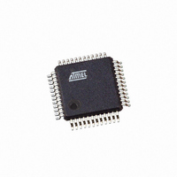
AT91SAM7S32B-AU-999 Atmel, AT91SAM7S32B-AU-999 Datasheet - Page 773

AT91SAM7S32B-AU-999
Manufacturer Part Number
AT91SAM7S32B-AU-999
Description
IC MCU ARM7 32KB FLASH 48LQFP
Manufacturer
Atmel
Series
AT91SAMr
Datasheet
1.AT91SAM7S16-MU.pdf
(779 pages)
Specifications of AT91SAM7S32B-AU-999
Core Processor
ARM7
Core Size
16/32-Bit
Speed
55MHz
Connectivity
I²C, SPI, SSC, UART/USART
Peripherals
Brown-out Detect/Reset, DMA, POR, PWM, WDT
Number Of I /o
21
Program Memory Size
32KB (32K x 8)
Program Memory Type
FLASH
Ram Size
8K x 8
Voltage - Supply (vcc/vdd)
1.65 V ~ 1.95 V
Data Converters
A/D 8x10b
Oscillator Type
Internal
Operating Temperature
-40°C ~ 85°C
Package / Case
48-LQFP
Processor Series
AT91SAMx
Core
ARM7TDMI
Data Bus Width
32 bit
Data Ram Size
8 KB
Interface Type
I2C, JTAG, SPI, USART
Maximum Clock Frequency
55 MHz
Number Of Programmable I/os
21
Operating Supply Voltage
3.3 V
Maximum Operating Temperature
+ 85 C
Mounting Style
SMD/SMT
3rd Party Development Tools
JTRACE-ARM-2M, KSK-AT91SAM7S-PL, MDK-ARM, RL-ARM, ULINK2
Development Tools By Supplier
AT91SAM-ICE, AT91-ISP, AT91SAM7S-EK
Minimum Operating Temperature
- 40 C
For Use With
AT91SAM-ICE - EMULATOR FOR AT91 ARM7/ARM9AT91SAM7S-EK - KIT EVAL FOR ARM AT91SAM7S
Lead Free Status / RoHS Status
Lead free / RoHS Compliant
Eeprom Size
-
Lead Free Status / Rohs Status
Details
Available stocks
Company
Part Number
Manufacturer
Quantity
Price
- Current page: 773 of 779
- Download datasheet (11Mb)
6175K–ATARM–30-Aug-10
12 Debug and Test Features ...................................................................... 47
13 Reset Controller (RSTC) ........................................................................ 57
14 Real-time Timer (RTT) ............................................................................ 73
15 Periodic Interval Timer (PIT) ................................................................. 81
16 Watchdog Timer (WDT) ......................................................................... 89
17 Voltage Regulator Mode Controller (VREG) ........................................ 95
18 Memory Controller (MC) ........................................................................ 97
12.1
12.2
12.3
12.4
12.5
13.1
13.2
13.3
13.4
14.1
14.2
14.3
14.4
15.1
15.2
15.3
15.4
16.1
16.2
16.3
16.4
17.1
17.2
18.1
18.2
18.3
18.4
Description .......................................................................................................47
Block Diagram .................................................................................................47
Application Examples ......................................................................................48
Debug and Test Pin Description ......................................................................50
Functional Description .....................................................................................51
Overview ..........................................................................................................57
Block Diagram .................................................................................................57
Functional Description .....................................................................................58
Reset Controller (RSTC) User Interface ..........................................................68
Overview ..........................................................................................................73
Block Diagram .................................................................................................73
Functional Description .....................................................................................73
Real-time Timer (RTT) User Interface .............................................................75
Overview ..........................................................................................................81
Block Diagram .................................................................................................81
Functional Description .....................................................................................82
Periodic Interval Timer (PIT) User Interface ....................................................84
Overview ..........................................................................................................89
Block Diagram .................................................................................................89
Functional Description .....................................................................................90
Watchdog Timer (WDT) User Interface ...........................................................92
Overview ..........................................................................................................95
Voltage Regulator Power Controller (VREG) User Interface ...........................96
Overview ..........................................................................................................97
Block Diagram .................................................................................................97
Functional Description .....................................................................................98
Memory Controller (MC) User Interface ........................................................101
AT91SAM7S Series Preliminary
763
Related parts for AT91SAM7S32B-AU-999
Image
Part Number
Description
Manufacturer
Datasheet
Request
R

Part Number:
Description:
Manufacturer:
ATMEL Corporation
Datasheet:

Part Number:
Description:
IC ARM7 MCU 32BIT 32K 48LQFP
Manufacturer:
Atmel
Datasheet:

Part Number:
Description:
AT91 ARM Thumb-based Microcontrollers
Manufacturer:
ATMEL [ATMEL Corporation]
Datasheet:

Part Number:
Description:
IC ARM7 MCU FLASH 32K 48QFN
Manufacturer:
Atmel
Datasheet:

Part Number:
Description:
IC MCU ARM7 32KB FLASH 48LQFP
Manufacturer:
Atmel
Datasheet:

Part Number:
Description:
IC MCU ARM7 32KB FLASH 48-VQFN
Manufacturer:
Atmel
Datasheet:

Part Number:
Description:
DEV KIT FOR AVR/AVR32
Manufacturer:
Atmel
Datasheet:

Part Number:
Description:
INTERVAL AND WIPE/WASH WIPER CONTROL IC WITH DELAY
Manufacturer:
ATMEL Corporation
Datasheet:

Part Number:
Description:
Low-Voltage Voice-Switched IC for Hands-Free Operation
Manufacturer:
ATMEL Corporation
Datasheet:

Part Number:
Description:
MONOLITHIC INTEGRATED FEATUREPHONE CIRCUIT
Manufacturer:
ATMEL Corporation
Datasheet:

Part Number:
Description:
AM-FM Receiver IC U4255BM-M
Manufacturer:
ATMEL Corporation
Datasheet:

Part Number:
Description:
Monolithic Integrated Feature Phone Circuit
Manufacturer:
ATMEL Corporation
Datasheet:

Part Number:
Description:
Multistandard Video-IF and Quasi Parallel Sound Processing
Manufacturer:
ATMEL Corporation
Datasheet:


