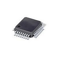
ATMEGA88PV-10AU Atmel, ATMEGA88PV-10AU Datasheet - Page 185

ATMEGA88PV-10AU
Manufacturer Part Number
ATMEGA88PV-10AU
Description
MCU AVR 8K ISP FLSH 10MHZ 32TQFP
Manufacturer
Atmel
Series
AVR® ATmegar
Specifications of ATMEGA88PV-10AU
Core Processor
AVR
Core Size
8-Bit
Speed
10MHz
Connectivity
I²C, SPI, UART/USART
Peripherals
Brown-out Detect/Reset, POR, PWM, WDT
Number Of I /o
23
Program Memory Size
8KB (4K x 16)
Program Memory Type
FLASH
Eeprom Size
512 x 8
Ram Size
1K x 8
Voltage - Supply (vcc/vdd)
1.8 V ~ 5.5 V
Data Converters
A/D 8x10b
Oscillator Type
Internal
Operating Temperature
-40°C ~ 85°C
Package / Case
32-TQFP, 32-VQFP
Processor Series
ATMEGA8x
Core
AVR8
Data Bus Width
8 bit
Data Ram Size
1 KB
Interface Type
SPI, TWI, UART
Maximum Clock Frequency
10 MHz
Number Of Programmable I/os
23
Number Of Timers
3
Operating Supply Voltage
1.8 V to 5.5 V
Maximum Operating Temperature
+ 85 C
Mounting Style
SMD/SMT
Minimum Operating Temperature
- 40 C
On-chip Adc
10 bit, 8 Channel
Package
32TQFP
Device Core
AVR
Family Name
ATmega
Maximum Speed
10 MHz
Controller Family/series
AVR MEGA
No. Of I/o's
23
Eeprom Memory Size
512Byte
Ram Memory Size
1KB
Cpu Speed
10MHz
Rohs Compliant
Yes
For Use With
ATAVRDRAGON - KIT DRAGON 32KB FLASH MEM AVRATAVRISP2 - PROGRAMMER AVR IN SYSTEM
Lead Free Status / RoHS Status
Lead free / RoHS Compliant
Available stocks
Company
Part Number
Manufacturer
Quantity
Price
- Current page: 185 of 420
- Download datasheet (9Mb)
19.7.2
8025L–AVR–7/10
Receiving Frames with 9 Data Bits
bits of the data read from the UDRn will be masked to zero. The USART has to be initialized
before the function can be used.
Note:
The function simply waits for data to be present in the receive buffer by checking the RXCn Flag,
before reading the buffer and returning the value.
If 9-bit characters are used (UCSZn=7) the ninth bit must be read from the RXB8n bit in
UCSRnB before reading the low bits from the UDRn. This rule applies to the FEn, DORn and
UPEn Status Flags as well. Read status from UCSRnA, then data from UDRn. Reading the
UDRn I/O location will change the state of the receive buffer FIFO and consequently the TXB8n,
FEn, DORn and UPEn bits, which all are stored in the FIFO, will change.
The following code example shows a simple USART receive function that handles both nine bit
characters and the status bits.
Assembly Code Example
C Code Example
USART_Receive:
unsigned char USART_Receive( void )
{
}
; Wait for data to be received
sbis UCSRnA, RXCn
rjmp USART_Receive
; Get and return received data from buffer
in
ret
/* Wait for data to be received */
while ( !(UCSRnA & (1<<RXCn)) )
/* Get and return received data from buffer */
return UDRn;
1.
See ”About Code Examples” on page 8.
For I/O Registers located in extended I/O map, “IN”, “OUT”, “SBIS”, “SBIC”, “CBI”, and “SBI”
instructions must be replaced with instructions that allow access to extended I/O. Typically
“LDS” and “STS” combined with “SBRS”, “SBRC”, “SBR”, and “CBR”.
r16, UDRn
;
(1)
(1)
ATmega48P/88P/168P
185
Related parts for ATMEGA88PV-10AU
Image
Part Number
Description
Manufacturer
Datasheet
Request
R

Part Number:
Description:
Manufacturer:
Atmel Corporation
Datasheet:

Part Number:
Description:
MCU AVR 8K ISP FLSH 20MHZ 32TQFP
Manufacturer:
Atmel
Datasheet:

Part Number:
Description:
MCU AVR 8K ISP FLASH 20MHZ 32QFN
Manufacturer:
Atmel
Datasheet:

Part Number:
Description:
MCU AVR 8K ISP FLASH 20MHZ 28DIP
Manufacturer:
Atmel
Datasheet:

Part Number:
Description:
MCU AVR 8KB FLASH 20MHZ 32TQFP
Manufacturer:
Atmel
Datasheet:

Part Number:
Description:
MCU AVR 8KB FLASH 20MHZ 32QFN
Manufacturer:
Atmel
Datasheet:

Part Number:
Description:
Atmega88p 8-bit Microcontroller With 8k Bytes In-system Programmable Flash
Manufacturer:
ATMEL Corporation
Datasheet:

Part Number:
Description:
IC MCU AVR 8K 5V 20MHZ 32-TQFP
Manufacturer:
Atmel
Datasheet:

Part Number:
Description:
Manufacturer:
Atmel Corporation
Datasheet:

Part Number:
Description:
Manufacturer:
Atmel Corporation
Datasheet:

Part Number:
Description:
MCU AVR 8K FLASH 15MHZ 32-QFN
Manufacturer:
Atmel
Datasheet:

Part Number:
Description:
IC AVR MCU 8K 20MHZ 5V 32TQFP
Manufacturer:
Atmel
Datasheet:

Part Number:
Description:
IC AVR MCU 8K 20MHZ 5V 32-QFN
Manufacturer:
Atmel
Datasheet:


