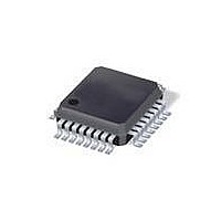
ATMEGA88PV-10AU Atmel, ATMEGA88PV-10AU Datasheet - Page 217

ATMEGA88PV-10AU
Manufacturer Part Number
ATMEGA88PV-10AU
Description
MCU AVR 8K ISP FLSH 10MHZ 32TQFP
Manufacturer
Atmel
Series
AVR® ATmegar
Specifications of ATMEGA88PV-10AU
Core Processor
AVR
Core Size
8-Bit
Speed
10MHz
Connectivity
I²C, SPI, UART/USART
Peripherals
Brown-out Detect/Reset, POR, PWM, WDT
Number Of I /o
23
Program Memory Size
8KB (4K x 16)
Program Memory Type
FLASH
Eeprom Size
512 x 8
Ram Size
1K x 8
Voltage - Supply (vcc/vdd)
1.8 V ~ 5.5 V
Data Converters
A/D 8x10b
Oscillator Type
Internal
Operating Temperature
-40°C ~ 85°C
Package / Case
32-TQFP, 32-VQFP
Processor Series
ATMEGA8x
Core
AVR8
Data Bus Width
8 bit
Data Ram Size
1 KB
Interface Type
SPI, TWI, UART
Maximum Clock Frequency
10 MHz
Number Of Programmable I/os
23
Number Of Timers
3
Operating Supply Voltage
1.8 V to 5.5 V
Maximum Operating Temperature
+ 85 C
Mounting Style
SMD/SMT
Minimum Operating Temperature
- 40 C
On-chip Adc
10 bit, 8 Channel
Package
32TQFP
Device Core
AVR
Family Name
ATmega
Maximum Speed
10 MHz
Controller Family/series
AVR MEGA
No. Of I/o's
23
Eeprom Memory Size
512Byte
Ram Memory Size
1KB
Cpu Speed
10MHz
Rohs Compliant
Yes
For Use With
ATAVRDRAGON - KIT DRAGON 32KB FLASH MEM AVRATAVRISP2 - PROGRAMMER AVR IN SYSTEM
Lead Free Status / RoHS Status
Lead free / RoHS Compliant
Available stocks
Company
Part Number
Manufacturer
Quantity
Price
- Current page: 217 of 420
- Download datasheet (9Mb)
8025L–AVR–7/10
• Different masters may use different SCL frequencies. A scheme must be devised to
The wired-ANDing of the bus lines is used to solve both these problems. The serial clocks from
all masters will be wired-ANDed, yielding a combined clock with a high period equal to the one
from the Master with the shortest high period. The low period of the combined clock is equal to
the low period of the Master with the longest low period. Note that all masters listen to the SCL
line, effectively starting to count their SCL high and low time-out periods when the combined
SCL line goes high or low, respectively.
Figure 21-7. SCL Synchronization Between Multiple Masters
Arbitration is carried out by all masters continuously monitoring the SDA line after outputting
data. If the value read from the SDA line does not match the value the Master had output, it has
lost the arbitration. Note that a Master can only lose arbitration when it outputs a high SDA value
while another Master outputs a low value. The losing Master should immediately go to Slave
mode, checking if it is being addressed by the winning Master. The SDA line should be left high,
but losing masters are allowed to generate a clock signal until the end of the current data or
address packet. Arbitration will continue until only one Master remains, and this may take many
bits. If several masters are trying to address the same Slave, arbitration will continue into the
data packet.
masters have started transmission at the same time should not be detectable to the slaves, i.e.
the data being transferred on the bus must not be corrupted.
synchronize the serial clocks from all masters, in order to let the transmission proceed in a
lockstep fashion. This will facilitate the arbitration process.
SCL from
SCL from
Master A
Master B
SCL Bus
Line
TA
Counting Low Period
low
Masters Start
TB
low
ATmega48P/88P/168P
TA
Counting High Period
high
Masters Start
TB
high
217
Related parts for ATMEGA88PV-10AU
Image
Part Number
Description
Manufacturer
Datasheet
Request
R

Part Number:
Description:
Manufacturer:
Atmel Corporation
Datasheet:

Part Number:
Description:
MCU AVR 8K ISP FLSH 20MHZ 32TQFP
Manufacturer:
Atmel
Datasheet:

Part Number:
Description:
MCU AVR 8K ISP FLASH 20MHZ 32QFN
Manufacturer:
Atmel
Datasheet:

Part Number:
Description:
MCU AVR 8K ISP FLASH 20MHZ 28DIP
Manufacturer:
Atmel
Datasheet:

Part Number:
Description:
MCU AVR 8KB FLASH 20MHZ 32TQFP
Manufacturer:
Atmel
Datasheet:

Part Number:
Description:
MCU AVR 8KB FLASH 20MHZ 32QFN
Manufacturer:
Atmel
Datasheet:

Part Number:
Description:
Atmega88p 8-bit Microcontroller With 8k Bytes In-system Programmable Flash
Manufacturer:
ATMEL Corporation
Datasheet:

Part Number:
Description:
IC MCU AVR 8K 5V 20MHZ 32-TQFP
Manufacturer:
Atmel
Datasheet:

Part Number:
Description:
Manufacturer:
Atmel Corporation
Datasheet:

Part Number:
Description:
Manufacturer:
Atmel Corporation
Datasheet:

Part Number:
Description:
MCU AVR 8K FLASH 15MHZ 32-QFN
Manufacturer:
Atmel
Datasheet:

Part Number:
Description:
IC AVR MCU 8K 20MHZ 5V 32TQFP
Manufacturer:
Atmel
Datasheet:

Part Number:
Description:
IC AVR MCU 8K 20MHZ 5V 32-QFN
Manufacturer:
Atmel
Datasheet:


