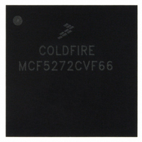
MCF5272CVF66 Freescale Semiconductor, MCF5272CVF66 Datasheet - Page 253

MCF5272CVF66
Manufacturer Part Number
MCF5272CVF66
Description
IC MPU 32BIT 66MHZ 196-MAPBGA
Manufacturer
Freescale Semiconductor
Series
MCF527xr
Specifications of MCF5272CVF66
Core Processor
Coldfire V2
Core Size
32-Bit
Speed
66MHz
Connectivity
EBI/EMI, Ethernet, I²C, SPI, UART/USART, USB
Peripherals
DMA, WDT
Number Of I /o
32
Program Memory Size
16KB (4K x 32)
Program Memory Type
ROM
Ram Size
1K x 32
Voltage - Supply (vcc/vdd)
3 V ~ 3.6 V
Oscillator Type
External
Operating Temperature
-40°C ~ 85°C
Package / Case
196-MAPBGA
Family Name
MCF5xxx
Device Core
ColdFire
Device Core Size
32b
Frequency (max)
66MHz
Instruction Set Architecture
RISC
Supply Voltage 1 (typ)
3.3V
Operating Temp Range
-40C to 85C
Operating Temperature Classification
Industrial
Mounting
Surface Mount
Pin Count
196
Package Type
MA-BGA
Lead Free Status / RoHS Status
Contains lead / RoHS non-compliant
Eeprom Size
-
Data Converters
-
Lead Free Status / Rohs Status
Not Compliant
Available stocks
Company
Part Number
Manufacturer
Quantity
Price
Company:
Part Number:
MCF5272CVF66
Manufacturer:
Freescale Semiconductor
Quantity:
10 000
Part Number:
MCF5272CVF66
Manufacturer:
FREESCALE
Quantity:
20 000
Company:
Part Number:
MCF5272CVF66 K75N
Manufacturer:
ST
Quantity:
18
Company:
Part Number:
MCF5272CVF66J
Manufacturer:
Freescale Semiconductor
Quantity:
10 000
- Current page: 253 of 544
- Download datasheet (7Mb)
11.6.1
The data for the fast Ethernet frames must reside in memory external to the FEC. The data for a frame is
placed in one or more buffers. Each buffer has a pointer to it in a buffer descriptor (BD). In addition to
pointing to the buffer, the BD contains the current state of the buffer. To permit maximum user flexibility,
the BDs are also located in external memory.
Software defines buffers by allocating/initializing memory and initializing buffer descriptors. Setting the
RxBD[E] or TxBD[R] produces the buffer. Software writing to either TDAR or RDAR tells the FEC that
a buffer has been placed in external memory for the transmit or receive data traffic, respectively. The
hardware reads the BDs and processes the buffers after they have been defined. After the data DMA is
complete and the BDs have been written by the DMA engine, RxBD[E] or TxBD[R] are cleared by
hardware to indicate that the buffer has been processed. Software may poll the BDs to detect when the
buffers have been processed or may rely on the buffer/frame interrupts.
The ETHER_EN signal operates as a reset to the BD/DMA logic. When ETHER_EN is negated, the DMA
engine BD pointers are reset to point to the starting transmit and receive BDs. The buffer descriptors are
not initialized by hardware during reset. At least one transmit and receive BD must be initialized by
software (write 0x0000_0000 to the most significant word of buffer descriptor) before the ETHER_EN bit
is set.
The BDs are organized in two separate rings, one for receive buffers and one for transmit buffers. ERDSR
defines the starting address of the receive BDs and ETDSR the same for the transmit BDs. The last buffer
descriptor in each ring is defined by the wrap (W) bit. When set, W indicates that the next descriptor in the
ring is at the location pointed to by ERDSR and ETDSR for the receive and transmit rings, respectively.
Buffers descriptor rings must start on a double-word boundary.
The format of the transmit and receive buffer descriptors are given in
11.6.1.1
In the RxBD, the user initializes the E and W bits in the first word and the pointer in the second word.
When the buffer has been sent as a DMA, the FEC will modify the E, L, M, LG, NO, SH, CR, and OV bits
and write the length of the used portion of the buffer in the first word. The M, LG, NO, SH, CR, and OV
bits in the first word of the buffer descriptor are modified by the FEC only when the L bit is set.
The first word of the RxBD contains control and status bits. Its format is detailed below.
Freescale Semiconductor
+0
+2
+4
+6
15
FEC Buffer Descriptor Tables
E
Ethernet Receive Buffer Descriptor (RxBD)
RO1
14
MCF5272 ColdFire
W
13
RO2
12
Figure 11-27. Receive Buffer Descriptor (RxBD)
11
L
®
Integrated Microprocessor User’s Manual, Rev. 3
10
Rx Data Buffer Pointer A[31–16]
Rx Data Buffer Pointer A[15–0]
—
9
DATA LENGTH
M
8
BC
7
MC
6
LG
5
Figure 11-27
NO
4
SH
3
and
CR
2
Figure
OV
Ethernet Module
1
11-28.
TR
0
11-35
Related parts for MCF5272CVF66
Image
Part Number
Description
Manufacturer
Datasheet
Request
R
Part Number:
Description:
Mcf5272 Coldfire Integrated Microprocessor User
Manufacturer:
Freescale Semiconductor, Inc
Datasheet:

Part Number:
Description:
MCF5272 Interrupt Service Routine for the Physical Layer Interface Controller
Manufacturer:
Freescale Semiconductor / Motorola
Datasheet:
Part Number:
Description:
Manufacturer:
Freescale Semiconductor, Inc
Datasheet:
Part Number:
Description:
Manufacturer:
Freescale Semiconductor, Inc
Datasheet:
Part Number:
Description:
Manufacturer:
Freescale Semiconductor, Inc
Datasheet:
Part Number:
Description:
Manufacturer:
Freescale Semiconductor, Inc
Datasheet:
Part Number:
Description:
Manufacturer:
Freescale Semiconductor, Inc
Datasheet:
Part Number:
Description:
Manufacturer:
Freescale Semiconductor, Inc
Datasheet:
Part Number:
Description:
Manufacturer:
Freescale Semiconductor, Inc
Datasheet:
Part Number:
Description:
Manufacturer:
Freescale Semiconductor, Inc
Datasheet:
Part Number:
Description:
Manufacturer:
Freescale Semiconductor, Inc
Datasheet:
Part Number:
Description:
Manufacturer:
Freescale Semiconductor, Inc
Datasheet:
Part Number:
Description:
Manufacturer:
Freescale Semiconductor, Inc
Datasheet:
Part Number:
Description:
Manufacturer:
Freescale Semiconductor, Inc
Datasheet:
Part Number:
Description:
Manufacturer:
Freescale Semiconductor, Inc
Datasheet:


