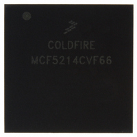
MCF5214CVF66 Freescale Semiconductor, MCF5214CVF66 Datasheet - Page 467

MCF5214CVF66
Manufacturer Part Number
MCF5214CVF66
Description
IC MPU 32BIT COLDF 256-MAPBGA
Manufacturer
Freescale Semiconductor
Series
MCF521xr
Datasheet
1.MCF5216CVM66J.pdf
(766 pages)
Specifications of MCF5214CVF66
Core Processor
Coldfire V2
Core Size
32-Bit
Speed
66MHz
Connectivity
CAN, EBI/EMI, I²C, SPI, UART/USART
Peripherals
DMA, LVD, POR, PWM, WDT
Number Of I /o
142
Program Memory Size
256KB (256K x 8)
Program Memory Type
FLASH
Ram Size
64K x 8
Voltage - Supply (vcc/vdd)
2.7 V ~ 3.6 V
Data Converters
A/D 8x12b
Oscillator Type
Internal
Operating Temperature
-40°C ~ 85°C
Package / Case
256-MAPBGA
Package
256MA-BGA
Device Core
ColdFire
Family Name
MCF521x
Maximum Speed
66 MHz
Operating Supply Voltage
3.3 V
Data Bus Width
32 Bit
Number Of Programmable I/os
142
Interface Type
QSPI/UART/I2C/CAN
On-chip Adc
8-chx10-bit
Number Of Timers
8
Lead Free Status / RoHS Status
Contains lead / RoHS non-compliant
Eeprom Size
-
Available stocks
Company
Part Number
Manufacturer
Quantity
Price
Company:
Part Number:
MCF5214CVF66
Manufacturer:
Freescale Semiconductor
Quantity:
10 000
Company:
Part Number:
MCF5214CVF66J
Manufacturer:
Freescale Semiconductor
Quantity:
10 000
- Current page: 467 of 766
- Download datasheet (9Mb)
processor may need to wait until the I2C is busy after writing the calling address to the I2DR before
proceeding with the following instructions.
The following example signals START and transmits the first byte of data (slave address):
24.4.3
Sending or receiving a byte sets the I2SR[ICF], which indicates one byte communication is finished.
I2SR[IIF] is also set. An interrupt is generated if the interrupt function is enabled during initialization by
setting I2CR[IIEN]. Software must first clear I2SR[IIF] in the interrupt routine. Reading from I2DR in
receive mode or writing to I2DR in transmit mode can clear I2SR[ICF].
Software can service the I
disabled. Polling should monitor IIF rather than ICF, because that operation is different when arbitration
is lost.
When an interrupt occurs at the end of the address cycle, the master is always in transmit mode; the address
is sent. If master receive mode is required, I2CR[MTX] should be toggled.
During slave-mode address cycles (I2SR[IAAS] = 1), I2SR[SRW] is read to determine the direction of the
next transfer. MTX is programmed accordingly. For slave-mode data cycles (IAAS = 0), SRW is invalid.
MTX should be read to determine the current transfer direction.
The following is an example of a software response by a master transmitter in the interrupt routine (see
Figure
24.4.4
A data transfer ends when the master signals a STOP, which can occur after all data is sent, as in the
following example.
Freescale Semiconductor
1. Check I2SR[IBB]. If it is set, wait until it is clear.
2. After cleared, set to transmit mode by setting I2CR[MTX].
3. Set master mode by setting I2CR[MSTA]. This generates a START condition.
4. Transmit the calling address via the I2DR.
5. Check I2SR[IBB]. If it is clear, wait until it is set and go to step #1.
1. Clear the I2CR[IIF] flag.
2. Check if acknowledge has been received, I2SR[RXAK].
3. If no ACK, end transmission. Else, transmit next byte of data via I2DR.
1. Check if acknowledge has been received, I2SR[RXAK]. If no ACK, end transmission and go to
2. Get value from transmitting counter, TXCNT. If no more data, go to step #5.
3. Transmit next byte of data via I2DR.
4. Decrement TXCNT and go to step #1
5. Generate a stop condition by clearing I2CR[MSTA].
24-14).
step #5.
Post-Transfer Software Response
Generation of STOP
MCF5282 and MCF5216 ColdFire Microcontroller User’s Manual, Rev. 3
2
C I/O in the main program by monitoring the IIF bit if the interrupt function is
I
2
C Interface
24-13
Related parts for MCF5214CVF66
Image
Part Number
Description
Manufacturer
Datasheet
Request
R
Part Number:
Description:
Manufacturer:
Freescale Semiconductor, Inc
Datasheet:
Part Number:
Description:
Manufacturer:
Freescale Semiconductor, Inc
Datasheet:
Part Number:
Description:
Manufacturer:
Freescale Semiconductor, Inc
Datasheet:
Part Number:
Description:
Manufacturer:
Freescale Semiconductor, Inc
Datasheet:
Part Number:
Description:
Manufacturer:
Freescale Semiconductor, Inc
Datasheet:
Part Number:
Description:
Manufacturer:
Freescale Semiconductor, Inc
Datasheet:
Part Number:
Description:
Manufacturer:
Freescale Semiconductor, Inc
Datasheet:
Part Number:
Description:
Manufacturer:
Freescale Semiconductor, Inc
Datasheet:
Part Number:
Description:
Manufacturer:
Freescale Semiconductor, Inc
Datasheet:
Part Number:
Description:
Manufacturer:
Freescale Semiconductor, Inc
Datasheet:
Part Number:
Description:
Manufacturer:
Freescale Semiconductor, Inc
Datasheet:
Part Number:
Description:
Manufacturer:
Freescale Semiconductor, Inc
Datasheet:
Part Number:
Description:
Manufacturer:
Freescale Semiconductor, Inc
Datasheet:
Part Number:
Description:
Manufacturer:
Freescale Semiconductor, Inc
Datasheet:
Part Number:
Description:
Manufacturer:
Freescale Semiconductor, Inc
Datasheet:


