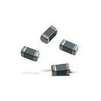
BLM18AG151SH1D Murata, BLM18AG151SH1D Datasheet - Page 27

BLM18AG151SH1D
Manufacturer Part Number
BLM18AG151SH1D
Description
EMI/RFI Suppressors & Ferrites 0603 150ohms Gen Use Tape
Manufacturer
Murata
Series
BLM Ar
Specifications of BLM18AG151SH1D
Shielding
Unshielded
Test Frequency
100 MHz
Product
Chip Ferrite Beads
Impedance
150 Ohms
Tolerance
25 %
Maximum Dc Current
200 mAmps
Maximum Dc Resistance
0.25 Ohms
Operating Temperature Range
- 55 C to + 125 C
Package / Case
0603 (1608 metric)
Termination Style
SMD/SMT
Lead Free Status / RoHS Status
Lead free / RoHS Compliant
Available stocks
Company
Part Number
Manufacturer
Quantity
Price
Company:
Part Number:
BLM18AG151SH1D
Manufacturer:
MURATA
Quantity:
240 000
3
!Note
!Note
3. Environmental Performance (Products should be soldered on the substrate.)
Table 1
4. Test Terminal (When measuring and supplying the voltage, the following terminal is applied.)
2
26
No.
No.
No.
Specifications and Test Methods
6
1
2
3
4
Insulation Resistance
Withstanding Voltage
1
2
3
4
5
Impedance Change
Continued from the preceding page.
Common Mode
• Please read rating and !CAUTION (for storage, operating, rating, soldering, mounting and handling) in this catalog to prevent smoking and/or burning, etc.
• This catalog has only typical specifications because there is no space for detailed specifications. Therefore, please approve our product specifications or transact the approval sheet for product specifications before ordering.
Please read rating and !CAUTION (for storage, operating, rating, soldering, mounting and handling) in this PDF catalog to prevent smoking and/or burning, etc.
This catalog has only typical specifications. Therefore, you are requested to approve our product specifications or to transact the approval sheet for product specifications before ordering.
Appearance
Vibration
Humidity
Heat Life
Cold Resistance
Temperature Cycle
Common Mode Impedance (Measurement Terminal)
Withstanding Voltage (Measurement Terminal)
DC Resistance (Measurement Terminal)
Insulation Resistance (Measurement Terminal)
Heat Life (Supply Terminal)
Item
Item
Item
No damage
No damage
within 20%
10M min.
Meet Table 1.
Meet Table 1.
Specifications
Specifications
Terminal
Terminal
Terminal
Terminal
Terminal
Terminal
Terminal
Terminal
Terminal
It should be soldered on the substrate.
Oscillation Frequency: 10 to 2000 to 10Hz for 20 min.
Total Amplitude 1.5mm or Acceleration amplitude 49m/s
whichever is smaller.
Testing Time: A period of 4 hrs. in each of 3 mutually
perpendicular directions. (Total 12 hrs.)
Temperature: 85 2 C
Humidity: 85%(RH)
Time: 1000 hrs. (+48 hrs., -0 hr.)
Then measured after exposure to room conditions for 4 to
48 hrs.
Temperature: 125 2 C
Applying Voltage: Rated Current
Time: 1000 hrs. (+48 hrs., -0 hr.)
Then measured after exposure to room conditions for 4 to
48 hrs.
Temperature: -40 2 C
Time: 1000 hrs. (+48 hrs., -0 hr.)
Then measured after exposure to room conditions for 4 to
48 hrs.
1 Cycle
Step 1 -40 C (+0 C, -3 C) / 30 3 minutes.
Step 2 Room Temperature / within 5 minutes.
Step 3 +125 C (+3 C, -0 C) / 30 3 minutes.
Step 4 Room Temperature / within 5 minutes.
Total of 1000 cycles
Then measured after exposure to room conditions for 4 to
48 hrs.
Terminal to be Tested
Test Methods
Test Methods
Terminal
Terminal
Terminal
C50E.pdf 05.1.28
2


