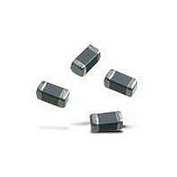
BLM18AG151SH1D Murata, BLM18AG151SH1D Datasheet - Page 38

BLM18AG151SH1D
Manufacturer Part Number
BLM18AG151SH1D
Description
EMI/RFI Suppressors & Ferrites 0603 150ohms Gen Use Tape
Manufacturer
Murata
Series
BLM Ar
Specifications of BLM18AG151SH1D
Shielding
Unshielded
Test Frequency
100 MHz
Product
Chip Ferrite Beads
Impedance
150 Ohms
Tolerance
25 %
Maximum Dc Current
200 mAmps
Maximum Dc Resistance
0.25 Ohms
Operating Temperature Range
- 55 C to + 125 C
Package / Case
0603 (1608 metric)
Termination Style
SMD/SMT
Lead Free Status / RoHS Status
Lead free / RoHS Compliant
Available stocks
Company
Part Number
Manufacturer
Quantity
Price
Company:
Part Number:
BLM18AG151SH1D
Manufacturer:
MURATA
Quantity:
240 000
!Note
!Note
2. Measurement Point and Noise Detection
3. Limits of CISPR 22/EN55022
(1) CISPR 22 recommends measurement at 10m distance.
CISPR 22/
EN55022
VCCI
FCC Part 15
V
Regulation
Continued from the preceding page.
However, other distance is acceptable if the limitation is
converted according to the following calculation.
Limitation shown left is converted to limitation for 3m
distance.
• Please read rating and !CAUTION (for storage, operating, rating, soldering, mounting and handling) in this catalog to prevent smoking and/or burning, etc.
• This catalog has only typical specifications because there is no space for detailed specifications. Therefore, please approve our product specifications or transact the approval sheet for product specifications before ordering.
Please read rating and !CAUTION (for storage, operating, rating, soldering, mounting and handling) in this PDF catalog to prevent smoking and/or burning, etc.
This catalog has only typical specifications. Therefore, you are requested to approve our product specifications or to transact the approval sheet for product specifications before ordering.
Limitation for
10m Distance
R
r
R
10
10
10
( V/m)
=20 log r
(dB
Radiated Interference
Main Interference Voltage
Radiated Interference
Main Interference Voltage
Radiated Interference
Main Interference Voltage
Measuring Item
V/m)
R
3
Short Repetition Period
10
=R
Conversion
r
3
10
= 10 r
+20 (1-log3)
3
10
Polarization and Measuring Point
Horizontal Pol. Vertical Pol.
AC Main Ports
Horizontal Pol. Vertical Pol.
AC Main Ports
Horizontal Pol. Vertical Pol.
AC Main Ports
Limitation for
3m Distance
R
r
R
3
3
3
( V/m)
=20 log r
(dB
Peak Detection
Quasi-Peak Detection
Average Detection
V/m)
3
PeakUQuasi-PeakUAverage
Outlines of Major Noise Regulation Standards
t
(Qp)
30M to 1GHz
150k to 30MHz
30M to 1GHz
150k to 30MHz
30M to 40GHz
150k to 30MHz
Frequency (Hz)
V
[Main Terminal Interference Voltage (Power Supply)]
[Radiated Interference]
On the border frequency, lower limit should be applied.
Class A Equipment: The equipment which is used in light
Class B Equipment: The equipment which is used in
90
70
50
30
90
70
50
30
10M
10k
Quasi-Peak Detection
Quasi-Peak Detection Mean Detection
Quasi-Peak Detection
Quasi-Peak Detection Mean Detection
Quasi-Peak Detection Mean Detection
Quasi-Peak Detection
50
40
30M
79
66
56
100k 150k 500k 1M
Long Repetition Period
Detection
class A
class B
industrial commercial areas.
residential areas.
Frequency [Hz]
Frequency [Hz]
56
46
100M
class A Quasi-peak value
class A Mean value
class B Quasi-peak value
class B Mean value
Continued on the following page.
230M
5M 10M 30M 100M
Antenna
Artificial Main Network
Dipole Antenna
Artificial Main Network
Antenna
Artificial Main Network
Measuring Devices
Peak Detection
Quasi-Peak Detection
Average Detection
C50E.pdf 05.1.28
57
47
73
60
50
1G
t
37


