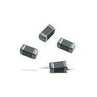
BLM18AG151SH1D Murata, BLM18AG151SH1D Datasheet - Page 30

BLM18AG151SH1D
Manufacturer Part Number
BLM18AG151SH1D
Description
EMI/RFI Suppressors & Ferrites 0603 150ohms Gen Use Tape
Manufacturer
Murata
Series
BLM Ar
Specifications of BLM18AG151SH1D
Shielding
Unshielded
Test Frequency
100 MHz
Product
Chip Ferrite Beads
Impedance
150 Ohms
Tolerance
25 %
Maximum Dc Current
200 mAmps
Maximum Dc Resistance
0.25 Ohms
Operating Temperature Range
- 55 C to + 125 C
Package / Case
0603 (1608 metric)
Termination Style
SMD/SMT
Lead Free Status / RoHS Status
Lead free / RoHS Compliant
Available stocks
Company
Part Number
Manufacturer
Quantity
Price
Company:
Part Number:
BLM18AG151SH1D
Manufacturer:
MURATA
Quantity:
240 000
!Note
!Note
1. Standard Land Pattern Dimensions
BLM18
NFM21
NFE61H
DLW31S
NFp series suppress noise by conducting the high-frequency noise element to ground. Therefore, to obtain maximum
performance from these filters, the ground pattern should be made as large as possible during the PCB design stage. As
shown in the right, one side of the PCB is used for chip mounting, and the other is used for grounding.
Small diameter feedthrough holes are then used to connect the grounds on each side of the PCB. This reduces the high-
frequency impedance of the grounding and maximizes the filter's performance.
• Please read rating and !CAUTION (for storage, operating, rating, soldering, mounting and handling) in this catalog to prevent smoking and/or burning, etc.
• This catalog has only typical specifications because there is no space for detailed specifications. Therefore, please approve our product specifications or transact the approval sheet for product specifications before ordering.
Please read rating and !CAUTION (for storage, operating, rating, soldering, mounting and handling) in this PDF catalog to prevent smoking and/or burning, etc.
This catalog has only typical specifications. Therefore, you are requested to approve our product specifications or to transact the approval sheet for product specifications before ordering.
oReflow and Flow
BLM Series
o Reflow Soldering
o Reflow Soldering
Chip mounting side
oReflow Soldering
NFM21H
BLM18
(except 18PG type)
Chip mounting side
Part Number
DLW31S
Type
8.8
2.0
4.8
a
b
3
Small diameter thru hole ø0.4
(Except BLMppP series)
a
b
Soldering
Reflow
Flow
0.6
a
DLW31S
Series
1.4
b
0.7
Size (mm)
a
2.6
Small diameter
thru hole ø0.4
c
2.2-2.6
1.8-2.0
1.6
a
a
b
c
b
3.7
0.8
b
d
0.4
0.7
c
c
2.3
1.6
g
d
Chip mounting side
• Do not apply narrower pattern than listed above to BLMppP.
o Flow Soldering (Except NFE61HT332)
Do not use gild pattern; excess soldering heat may dissolve
metal of a copper wire.
BLMppP
BLM18PG
Narrow pattern can cause excessive heat or open circuit.
The chip EMI filter suppress noise by conducting the high-
frequency noise to ground. Therefore, to get enough noise
reduction, feed through holes which are connected to ground-
plane should be arranged according to the figure to reinforce
the ground-pattern.
• NFM21 is specially adapted for reflow soldering.
1: If the pattern is made with wider than 1.6mm (DLW31S) it
2: If the pattern is made with less than 0.4mm, in the worst
3: If the pattern is made with wider than 1.6mm (DLW31S),
Type
may result in components turning around, because melting
speed is different. In the worst case, short circuit between
lines may occur.
case, short circuit between lines may occur due to spread
of soldering paste or mount placing accuracy.
the bending strength will be reduced.
Small diameter thru hole ø0.4
1.5
3.8
4.8
9.0
Current
0.5-1.5
Rated
(A)
2
3
Soldering and Mounting
a
b
Soldering
Reflow
Flow/
0.7
a
Continued on the following page.
2.2-2.6
Reflow
1.8-2.0
Flow
b
Land Pattern
+ Solder Resist
Land Pattern
Solder Resist
0.7
c
Land pad thickness
18 m 35 m 70 m
0.7
1.2
2.4
and dimension d
C50E.pdf 05.1.28
0.7
0.7
1.2
0.7
0.7
0.7
(in mm)
29
3


