HP75BNC12X Switchcraft Inc., HP75BNC12X Datasheet - Page 46
HP75BNC12X
Manufacturer Part Number
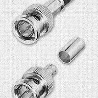
HP75BNC12X
Description
CONN BNC PLUG TRUE 75 OHM CRIMP
Manufacturer
Switchcraft Inc.
Series
BNCr
Type
BNCr
Datasheet
1.HP75BNC12X.pdf
(333 pages)
Specifications of HP75BNC12X
Impedance
75 Ohm
Rohs Information
Switchcraft RoHS Info.
Connector Style
BNC
Connector Type
Plug, Male Pins
Contact Termination
Crimp
Mounting Type
Free Hanging (In-Line)
Fastening Type
Bayonet Lock
Gender
M
Body Style
Straight
Terminate To
Coaxial Cable
Mounting Style
Cable
Termination
Crimp
Body Plating
Nickel
Contact Plating
Gold
Contact Material
Copper Alloy
Body Material
Copper Alloy
Product Length (mm)
25mm
Product
Connector
Rf Series
BNC
Polarity
Normal
Shell Plating
Nickel
Termination Style
Crimp
Cable Type
Belden 1417B, 1855A, 1865A, Gepco VDM230, VDM250, RGB230/250 Series, Comm/Scope 7537, 7538
Housing Material
Copper Alloy
Maximum Frequency
3 GHz
Lead Free Status / RoHS Status
Lead free / RoHS Compliant
Features
-
Frequency-max
-
Color
-
Cable Group
-
Lead Free Status / Rohs Status
Lead free / RoHS Compliant


FAX: 773 792 - 2129
SWITCHCRAFT, INC. 5555 N. Elston Ave. • Chicago, IL 60630
EN3
GENERAL FEATURES AND BENEFITS
• Great all-purpose connector “weather” or not sealing feature is required.
• Superior leakage protection. Contact area is double-sealed for
• Integral O-ring and gasket. O-ring is molded onto cord housing
• Reduced part count for reduced labor to assemble.
• No Grommets. Cable clamp assembly features living hinges,
• Thermoplastic rubber body simulates closed entry contact
• Abrasion-resistant thermoplastic boot provides strain relief
• Housing rated UL 94V-O against flammability.
• Panel connector shell features a positioning keyway to prevent
• 2-18 pins.
• Exceeds Coast Guard specifications for water tightness
• Optional cap covers panel housing assembly when not in use.
• Exceeds enclosure rating IP16/IP18 when not mated or
• Exceeds enclosure rating 6P at 1000V when mated or covered (NEMA 250).
MATING INSTRUCTIONS FOR A CORD CONNECTOR TO A
PANEL MOUNT OR IN-LINE CONNECTOR
First, align the notched keyway on both the panel mount or in-line and
cord connector. Then, push the cord connector onto the mating connector.
Grasp the coupling ring between the slots, push it toward the panel
mount connector and rotate it clockwise nearly one half a turn. Continue
rotating until you feel the coupling ring ride over the locking “bump”. This
is the locked position. The cord connector is not securely in place unless
this procedure is followed.
APPLICATIONS
Process Control
Marine Electronics
Medical Instrumentation
Geothermal Instrumentation
MATERIALS
Cord and panel connector shells, contact locking disk,
and cable clamp assembly: Thermoplastic polymer glass
fiber, flame retardant
Coupling ring: Nylon
Rear boot and connector shell interior: Thermoplastic rubber
Contacts: Copper base alloy gold-plated over nickel underplate
SPECIFICATIONS
MECHANICAL
Shock: Mil-Std 202 Method 213B, condition K
Vibration: Mil-Std 202 Method 201
Life: 600 insertion/withdrawal cycles (minimum)
ELECTRICAL
Voltage Rating (sea level): Tested at 600 VRMS
Insulation Resistance: 100 megohms (minimum) at 77° F
Contact Resistance: 5 milliohms (maximum)
Current Rating: 3.0 Amps (#26 contact)– 9 through 18pin
excellent moisture and chemical resistance when mated to
Switchcraft’s connectors.
assembly and gasket is molded onto panel housing assembly
to prevent leakage and eliminate need for additional O-rings
and gaskets.
which snap easily onto and support the cable.
system to prevent probe damage or accidental loss of
spring retention due to misaligned or bent pins.
and accepts cable diameter .195" to .265".
misalignments and a polarizing single “D” design for proper panel
mounting and to prevent rotational movement.
(CFR 46 Part 110.20).
covered and IP66/IP68 when mated or covered (IEC 529).
™
MINI WEATHERTIGHT CONNECTOR SERIES
6.5 Amps (#20 contact)– 7 and 8 pin
7.5 Amps (#20 contact)– 2 through 6 pin
13.0 Amps (#16 contact)– 2 and 3 pin
Communications
Transportation
General Industrial Electronics
Harsh Environments
DIMENSIONS ARE FOR REFERENCE ONLY
EN3 MINI WEATHERTIGHT CONNECTOR SERIES
EN3 MINI WEATHERTIGHT CONNECTOR SERIES
™
™
ENVIRONMENTAL
Temperature Limits: -40°C to +65°C (non-operating)
Moisture Resistance: Mil-Std 202 Method 106F
Insulation Resistance: Mil-Std 202 Method 302
condition B
Thermal Shock: Mil-Std 202 Method 107G
Salt Spray: Mil-Std 202 Method 101D condition B
RATINGS
IP16/IP18
IP66/IP68
NEMA 250 (6P)
Patent 5,485,673 File 36049
(mm)
Inch
50.00
40.00
30.00
20.00
10.00
0.00
EN3
™
Contact size/
number of contacts
7
Weathertight Connector Current Carry Capability
Dielectric Withstanding Voltage
#20-7, #20-8
#20-5, #20-6
CONNECTORS & RECEPTACLES
CFR 46 Part 110.20
UL 94V-O
#16-3
Current (Amps) - w/14 AWG Wire
(per UL 498 Standard)
10
#20-2
#20-4
#20-3
#16-2
Cord
Connector
Female 3 pin
Male 3 pin
12
Female 8 pin
Male 8 pin
Panel
Connector
Voltage
3000
2000
1000
13
15
41
Related parts for HP75BNC12X
Image
Part Number
Description
Manufacturer
Datasheet
Request
R

Part Number:
Description:
CONN PLUG PHONE 1/4" 2POS RED
Manufacturer:
Switchcraft Inc.
Datasheet:

Part Number:
Description:
CONN PLUG 2-COND 1/4" PHONE SLD
Manufacturer:
Switchcraft Inc.
Datasheet:

Part Number:
Description:
CONN PLUG PHONE SILENT 2-COND
Manufacturer:
Switchcraft Inc.
Datasheet:

Part Number:
Description:
THICK PANEL/GOLD PLA
Manufacturer:
Switchcraft Inc.
Datasheet:

Part Number:
Description:
CONN JACK PHONE 1/4" 2POS CLOSED
Manufacturer:
Switchcraft Inc.
Datasheet:

Part Number:
Description:
CONN PHONE JACK 2COND 1/4" OPEN
Manufacturer:
Switchcraft Inc.
Datasheet:
Part Number:
Description:
CONN JACK PHONE 1/4" 2POS W/HDWR
Manufacturer:
Switchcraft Inc.
Datasheet:

Part Number:
Description:
CONN PLUG PHONE .206" 2POS BLACK
Manufacturer:
Switchcraft Inc.
Datasheet:
Part Number:
Description:
CONN PLUG PHONE 1/4" FLAT 2POS
Manufacturer:
Switchcraft Inc.
Datasheet:

Part Number:
Description:
CONN PLUG FLAT PHONE 1/4" 3-COND
Manufacturer:
Switchcraft Inc.
Datasheet:

Part Number:
Description:
PHONE T-JACK PANEL .25" STD SGL
Manufacturer:
Switchcraft Inc.
Datasheet:

Part Number:
Description:
CONN JACK PANEL 96POS W/O JACK
Manufacturer:
Switchcraft Inc.
Datasheet:
Part Number:
Description:
CONN PLUG PHONE .206" 3POS BLACK
Manufacturer:
Switchcraft Inc.
Datasheet:

Part Number:
Description:
CONN JACK 1/4" 3-COND IN-LINE
Manufacturer:
Switchcraft Inc.
Datasheet:

Part Number:
Description:
CONN PLUG AUDIO PHONE 3COND BLK
Manufacturer:
Switchcraft Inc.
Datasheet: