HP75BNC12X Switchcraft Inc., HP75BNC12X Datasheet - Page 84
HP75BNC12X
Manufacturer Part Number
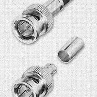
HP75BNC12X
Description
CONN BNC PLUG TRUE 75 OHM CRIMP
Manufacturer
Switchcraft Inc.
Series
BNCr
Type
BNCr
Datasheet
1.HP75BNC12X.pdf
(333 pages)
Specifications of HP75BNC12X
Impedance
75 Ohm
Rohs Information
Switchcraft RoHS Info.
Connector Style
BNC
Connector Type
Plug, Male Pins
Contact Termination
Crimp
Mounting Type
Free Hanging (In-Line)
Fastening Type
Bayonet Lock
Gender
M
Body Style
Straight
Terminate To
Coaxial Cable
Mounting Style
Cable
Termination
Crimp
Body Plating
Nickel
Contact Plating
Gold
Contact Material
Copper Alloy
Body Material
Copper Alloy
Product Length (mm)
25mm
Product
Connector
Rf Series
BNC
Polarity
Normal
Shell Plating
Nickel
Termination Style
Crimp
Cable Type
Belden 1417B, 1855A, 1865A, Gepco VDM230, VDM250, RGB230/250 Series, Comm/Scope 7537, 7538
Housing Material
Copper Alloy
Maximum Frequency
3 GHz
Lead Free Status / RoHS Status
Lead free / RoHS Compliant
Features
-
Frequency-max
-
Color
-
Cable Group
-
Lead Free Status / Rohs Status
Lead free / RoHS Compliant


FAX: 773 792 - 2129
SWITCHCRAFT, INC. 5555 N. Elston Ave. • Chicago, IL 60630
Single open circuit. (J1.)
Transfer circuit. (J5).
Single closed. Isolated
switching “make”
circuit. (J4-1A).
JACK SCHEMATICS
Circuit Types: Jacks normally have through circuits, shunt
circuits, and/or isolated switching circuits, either individually or
in various combinations. The chart below shows schematics of
39 common jacks - many more combinations are possible, but
these are the most commonly used. A basic description of the
switching action of each jack accompanies each schematic.
Military Identification: Military specifications covering phone
jacks use a special code to describe jack functions. Jack
schematic descriptions are coded J-1 through J-13 (as
appropriate) to coincide with Federal Item Identification
Guides for Supply Cataloging. One or more groups of suffix
numbers/letters identify isolated switching circuits used.
Suffixes identify the switching by industry recognized notation,
i.e., 1-A, 1-B, 1-C, 1-D, etc. See chart below.
Double open circuit.
Isolated switching–
separate “break” and
make circuits (J2-1A-1B).
Double open circuit.
Isolated switching–
separate “make”
circuits on both tip and
ring. (J2-2A).
Single closed circuit,
sleeve common. (J3).
Tip closed, ring
open. (J10).
Double closed
circuit. (J7).
Single closed circuit
Isolated switching
“break” circuit. (J4-1B).
Double closed circuit.
Isolated switching
“make” circuit on ring
spring. (J7-1A).
DIMENSIONS ARE FOR REFERENCE ONLY
Single closed circuit. (J4).
Tip closed, ring open
(common to sleeve). (J6).
Single closed circuit.
Isolated switching
transfer circuit. (J4-1C).
Single closed circuit–
“make” before
“break”. (J8).
Single closed circuit
plus “make” before
“break”. Isolated
switching–“make”
before “break”
circuit. (J8-1D).
NOTE: Number indicates the quantity of circuit - 2-A means 2, A circuits.
Terminals locations shown on jack schematics do not necessarily coincide
with physical locations on jacks. Not all circuit types available on all jacks.
Notation
1-A
1-B
1-C
1-D
(mm)
Inch
Double open circuit. (J2).
Single open circuit.
Isolated switching
“break” circuit. (J1-1B).
Double closed circuit.
Isolated switching
“break” circuit. (J7-1B).
Single open circuit.
Isolated switching
transfer circuit. (J1-1C).
Single open circuit.
Isolated switching–
separate transfer and
“make” circuits.
(J1-1A-1C).
One, SPST switching circuit. Also known as NO
(normally open) or “make” circuit.
One, SPST switching circuit. Also known as NC
(normally closed) or “break” circuit.
One, SPDT switching circuit. Also known as transfer
or “break” before “make” circuit.
One, SPDT switching circuit. Also known as “make”
before “break” circuit.
Meaning
JACKS AND PLUGS
JACK SCHEMATICS
JACK SCHEMATICS
Single open circuit.
Isolated switching
“make” circuit. (J1-1-A).
Double closed circuit,
ring common to
sleeve. (J13).
Double open circuit.
Isolated switching
transfer circuit. (J2-1C).
Double open circuit.
Isolated switching
“make” circuit.
(J2-1A).
Single closed circuit.
Isolated switching
“break” circuit. Sleeve
common to isolated
switching circuit throw.
(J4-1B).
79
Related parts for HP75BNC12X
Image
Part Number
Description
Manufacturer
Datasheet
Request
R

Part Number:
Description:
CONN PLUG PHONE 1/4" 2POS RED
Manufacturer:
Switchcraft Inc.
Datasheet:

Part Number:
Description:
CONN PLUG 2-COND 1/4" PHONE SLD
Manufacturer:
Switchcraft Inc.
Datasheet:

Part Number:
Description:
CONN PLUG PHONE SILENT 2-COND
Manufacturer:
Switchcraft Inc.
Datasheet:

Part Number:
Description:
THICK PANEL/GOLD PLA
Manufacturer:
Switchcraft Inc.
Datasheet:

Part Number:
Description:
CONN JACK PHONE 1/4" 2POS CLOSED
Manufacturer:
Switchcraft Inc.
Datasheet:

Part Number:
Description:
CONN PHONE JACK 2COND 1/4" OPEN
Manufacturer:
Switchcraft Inc.
Datasheet:
Part Number:
Description:
CONN JACK PHONE 1/4" 2POS W/HDWR
Manufacturer:
Switchcraft Inc.
Datasheet:

Part Number:
Description:
CONN PLUG PHONE .206" 2POS BLACK
Manufacturer:
Switchcraft Inc.
Datasheet:
Part Number:
Description:
CONN PLUG PHONE 1/4" FLAT 2POS
Manufacturer:
Switchcraft Inc.
Datasheet:

Part Number:
Description:
CONN PLUG FLAT PHONE 1/4" 3-COND
Manufacturer:
Switchcraft Inc.
Datasheet:

Part Number:
Description:
PHONE T-JACK PANEL .25" STD SGL
Manufacturer:
Switchcraft Inc.
Datasheet:

Part Number:
Description:
CONN JACK PANEL 96POS W/O JACK
Manufacturer:
Switchcraft Inc.
Datasheet:
Part Number:
Description:
CONN PLUG PHONE .206" 3POS BLACK
Manufacturer:
Switchcraft Inc.
Datasheet:

Part Number:
Description:
CONN JACK 1/4" 3-COND IN-LINE
Manufacturer:
Switchcraft Inc.
Datasheet:

Part Number:
Description:
CONN PLUG AUDIO PHONE 3COND BLK
Manufacturer:
Switchcraft Inc.
Datasheet: