HP75BNC12X Switchcraft Inc., HP75BNC12X Datasheet - Page 87
HP75BNC12X
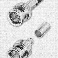
Manufacturer Part Number
HP75BNC12X
Description
CONN BNC PLUG TRUE 75 OHM CRIMP
Manufacturer
Switchcraft Inc.
Series
BNCr
Type
BNCr
Datasheet
1.HP75BNC12X.pdf
(333 pages)
Specifications of HP75BNC12X
Impedance
75 Ohm
Rohs Information
Switchcraft RoHS Info.
Connector Style
BNC
Connector Type
Plug, Male Pins
Contact Termination
Crimp
Mounting Type
Free Hanging (In-Line)
Fastening Type
Bayonet Lock
Gender
M
Body Style
Straight
Terminate To
Coaxial Cable
Mounting Style
Cable
Termination
Crimp
Body Plating
Nickel
Contact Plating
Gold
Contact Material
Copper Alloy
Body Material
Copper Alloy
Product Length (mm)
25mm
Product
Connector
Rf Series
BNC
Polarity
Normal
Shell Plating
Nickel
Termination Style
Crimp
Cable Type
Belden 1417B, 1855A, 1865A, Gepco VDM230, VDM250, RGB230/250 Series, Comm/Scope 7537, 7538
Housing Material
Copper Alloy
Maximum Frequency
3 GHz
Lead Free Status / RoHS Status
Lead free / RoHS Compliant
Features
-
Frequency-max
-
Color
-
Cable Group
-
Lead Free Status / Rohs Status
Lead free / RoHS Compliant


82
w w w . s w i t c h c r a f t . c o m
LONG FRAME TELEPHONE JACKS
JACKS AND PLUGS
LONG FRAME TELEPHONE JACKS
LONG FRAME TELEPHONE JACKS
Long frame jacks are designed especially for high quality
communication equipment, and to meet exacting MIL
specifications, as well as telephone and communication systems.
Many jacks have WEco equivalent types. MT-Jax
offered in four styles: MT-Jax
Rugged steel frames are produced in specially designed dies,
press welded to provide rigidity and dimensional stability required
by telephone and communication jack panels - and to meet MIL
frame strength tests. “A” and “C” frame styles are available.
TERMINALS –
nals. Wire-Wrapping Terminals: WMT-Jax
minals. Offset Ground Lugs: XMT-Jax
lugs, which simplify production line wiring time. A single row of
jacks can be installed with a single buss wire connected to all
ground lugs in a row, or when double rows are mounted on .625"
vertical centers with lugs oriented between rows, holes in ground
lugs line up so a single buss wire provides connections for both
rows. XMT-Jax
oriented toward jack frame. See illustration.
MIL STANDARDIZATION –
adjusted for use with plugs specified in Amendment No.1, MIL-P-642,
usually M642/1-1, M642/1-2, M642/2-1, M642/2-2, M642/4-1 or
M642/4-2. When applicable, specify the plug you will use; we will
adjust with that plug where the item is not a MIL-type. NOTE:
MT-Jax
(“A” Frame)
WMT-Jax
WMT-332B
Ground Lug “Toward”
Frame (Y Offset)
Buss Wire
Between
Rows
Ground Lug
“Toward” Frame
®
Details of Typical Buss Wiring of Jacks
®
, Number
®
have ground lugs oriented away and YMT-Jax
Solder Lug: All MT-Jax
with Offset Ground Lugs
MT-Jax
(“C” Frame)
Ground Lug “Away”
from Frame (X Offset)
®
, WMT-Jax
®
MIL jack types listed have been
®
and YMT-Jax
®
, XMT-Jax
®
XMT-Jax
XMT-332A
®
have wire-wrapping ter-
YMT-Jax
YMT-332B
have solder lug termi-
®
phone jacks are
®
DIMENSIONS ARE FOR REFERENCE ONLY
®
and YMT-Jax
®
, Number
Buss Wire
Outside of
Rows
®
have ground
, Number
®
are
®
.
MT-Jax
shorter bushings, 0.5" long with a hold inside diameter of
.21". They will mate with MIL plug M642/5-1 or M642/8-1.
M642/5-1 plug (Switchcraft
◊MT-342B or ◊MT-344B if these jacks are mounted on standard
.625" thick panels. The short jack bushings are recessed
.125", and the M642/5-1 is too wide to fit in the panel recess.
Use plug M642/8-1 (Switchcraft 484) with a narrower
diameter to fit in the recess and mate properly.
CONTACTS –
circuits are welded crossbar palladium. Welded crossbar gold
alloy contacts (WEco #1) are available on special order for dry
circuit applications.
SPECIFICATIONS
Frame and Stack Screws: Plated steel, with iridescent
iridite finish.
Springs: Copper alloy, spring tempered. Solder lugs are tinned.
Bushings: Plated copper alloy standard. Natural brass finish
optional.
Insulation: Rigid plastic spacers (MIL-type PBE-P per
Specification LP-513). One piece molded through stack.
Contacts: Welded crossbar palladium contacts in shunt and
isolated switching circuits are standard. Gold alloy (WEco #1)
and fine silver are available on special order.
MECHANICAL
Life: Commercial jacks: 10,000 insertion/withdrawal cycles, minimum.
Military Jacks: 20,000 insertion/withdrawal cycles, minimum.
Mechanical Shock: Military Jacks – Per MIL-STD-202,
method 213, Test Condition H (75g).
Vibration: Military Jacks – Per MIL-STD-202, method 213, (10-55 Hz).
ELECTRICAL
Contact Resistance: Commercial Jacks – .030 ohms
maximum (initial), .050 ohms maximum (after humidity, durability
exposure). Military Jacks – .010 ohms maximum (initial), .020
ohms maximum (after life), .10 ohms maximum (after salt spray).
Insulation Resistance: Commercial Jacks – 10,000 MΩ
minimum (initial), 1,000 MΩ minimum (after humidity). Military
Jacks – 10,000 MΩ minimum (initial), 1,000 MΩ minimum (after
humidity, durability exposure).
Dielectric Withstanding Voltage: 500 V, 60 Hz (rms) AC.
ENVIRONMENTAL
Thermal Range: Commercial Jacks – -55°C to +85°C
(non-operating); -20°C to +65°C (operating). Military Jacks -
-55°C to +85°C (non operating); -40°C to +65°C (operating).
Thermal Shock: Commercial Jacks – Per MIL-STD-202,
method 107. Military Jacks – Per MIL-STD-202, method 107.
Humidity: Commercial Jacks – Per MIL-STD-202, method
106. Military Jacks – 0% to 95% operating and non-operating.
Salt Spray: Commercial Jacks – Per MIL-STD-202, method
101. Military Jacks – Per MIL-STD-202, method 101 (48 hours).
Moisture Resistance: Military Jacks – Per MIL-STD-202,
method 106 (240 hours).
ORDERING –
in jacks are available on special order. Special circuitry, frames,
contacts, natural brass bushings, as other terminals are available.
®
Note: Contact your Switchcraft Representative for price and delivery
jacks Numbers ◊MT-342B and ◊MT-344B have
(mm)
Inch
Order jacks by part number. Additional variations
Contacts on shuts and isolated switching
PHONE: 773 792 - 2700
® Registered trademark of Switchcraft, Inc.
480) cannot be used with
Related parts for HP75BNC12X
Image
Part Number
Description
Manufacturer
Datasheet
Request
R

Part Number:
Description:
CONN PLUG PHONE 1/4" 2POS RED
Manufacturer:
Switchcraft Inc.
Datasheet:

Part Number:
Description:
CONN PLUG 2-COND 1/4" PHONE SLD
Manufacturer:
Switchcraft Inc.
Datasheet:

Part Number:
Description:
CONN PLUG PHONE SILENT 2-COND
Manufacturer:
Switchcraft Inc.
Datasheet:

Part Number:
Description:
THICK PANEL/GOLD PLA
Manufacturer:
Switchcraft Inc.
Datasheet:

Part Number:
Description:
CONN JACK PHONE 1/4" 2POS CLOSED
Manufacturer:
Switchcraft Inc.
Datasheet:

Part Number:
Description:
CONN PHONE JACK 2COND 1/4" OPEN
Manufacturer:
Switchcraft Inc.
Datasheet:
Part Number:
Description:
CONN JACK PHONE 1/4" 2POS W/HDWR
Manufacturer:
Switchcraft Inc.
Datasheet:

Part Number:
Description:
CONN PLUG PHONE .206" 2POS BLACK
Manufacturer:
Switchcraft Inc.
Datasheet:
Part Number:
Description:
CONN PLUG PHONE 1/4" FLAT 2POS
Manufacturer:
Switchcraft Inc.
Datasheet:

Part Number:
Description:
CONN PLUG FLAT PHONE 1/4" 3-COND
Manufacturer:
Switchcraft Inc.
Datasheet:

Part Number:
Description:
PHONE T-JACK PANEL .25" STD SGL
Manufacturer:
Switchcraft Inc.
Datasheet:

Part Number:
Description:
CONN JACK PANEL 96POS W/O JACK
Manufacturer:
Switchcraft Inc.
Datasheet:
Part Number:
Description:
CONN PLUG PHONE .206" 3POS BLACK
Manufacturer:
Switchcraft Inc.
Datasheet:

Part Number:
Description:
CONN JACK 1/4" 3-COND IN-LINE
Manufacturer:
Switchcraft Inc.
Datasheet:

Part Number:
Description:
CONN PLUG AUDIO PHONE 3COND BLK
Manufacturer:
Switchcraft Inc.
Datasheet: