HP75BNC12X Switchcraft Inc., HP75BNC12X Datasheet - Page 86
HP75BNC12X
Manufacturer Part Number
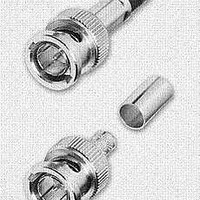
HP75BNC12X
Description
CONN BNC PLUG TRUE 75 OHM CRIMP
Manufacturer
Switchcraft Inc.
Series
BNCr
Type
BNCr
Datasheet
1.HP75BNC12X.pdf
(333 pages)
Specifications of HP75BNC12X
Impedance
75 Ohm
Rohs Information
Switchcraft RoHS Info.
Connector Style
BNC
Connector Type
Plug, Male Pins
Contact Termination
Crimp
Mounting Type
Free Hanging (In-Line)
Fastening Type
Bayonet Lock
Gender
M
Body Style
Straight
Terminate To
Coaxial Cable
Mounting Style
Cable
Termination
Crimp
Body Plating
Nickel
Contact Plating
Gold
Contact Material
Copper Alloy
Body Material
Copper Alloy
Product Length (mm)
25mm
Product
Connector
Rf Series
BNC
Polarity
Normal
Shell Plating
Nickel
Termination Style
Crimp
Cable Type
Belden 1417B, 1855A, 1865A, Gepco VDM230, VDM250, RGB230/250 Series, Comm/Scope 7537, 7538
Housing Material
Copper Alloy
Maximum Frequency
3 GHz
Lead Free Status / RoHS Status
Lead free / RoHS Compliant
Features
-
Frequency-max
-
Color
-
Cable Group
-
Lead Free Status / Rohs Status
Lead free / RoHS Compliant


FAX: 773 792 - 2129
SWITCHCRAFT, INC. 5555 N. Elston Ave. • Chicago, IL 60630
1/4" LONG FRAME TELEPHONE JACKS
JACK MATERIALS
The complete Switchcraft line of standard size panels,
jacks, plugs, switches and accessories are rugged, premium
quality devices...hand-crafted by experts...100% inspected...
and carefully adjusted to meet the traditionally high quality
demands of the telephone industry and the military. Tightly
controlled incoming inspection, manufacturing methods,
and QC procedures assure you of long-life, reliable components.
Typical applications where Switchcraft components have
been specified for more than five decades are: telephone
central office equipment, switchboards, jackfields, test
and patch panels, and station equipment; TV and radio
broadcasting consoles; PA and communication consoles;
telegraph systems and apparatus; multichannel video and
audio patching; and data processing equipment, such as
computers, telemetry, I/O devices and facsimile.
FRAMES –
press welded for added strength. Side member adds to
frame rigidity and resistance to shock and vibration. Both
“A” and “C” type frames can be supplied. (See next page.)
SPRINGS –
because it offers excellent mechanical and electrical
characteristics, and good corrosion resistance. The spring
alloy has special hardness and ductility, and springs are
produced from custom-designed dies. Although normally
adjusted to mate with telephone (and MIL-type) plugs, springs
can be adjusted to mate with commercial phone plugs.
BUSHINGS –
jacks), drilled to accept either a standard (.250" diameter
finger) plug or a popular smaller (.206" diameter finger)
plug. Series M Hi-D Jax
molded thermoplastic bushing for insulated mounting.
CONTACTS –
contacts for low resistance connections. The contacts
supplied depend on the jack selected. Gold or silver plating is
normally offered as an option on tip, ring and/or sleeve springs.
Several precious metals and shapes are used on jacks.
Palladium
Fine silver
Gold alloy
Crossbar
Fine silver
(Large)
Gold or
Silver
Material
A special copper alloy is used for leaf springs
Jack frames are heavy steel, formed and
Shape
Bushings are copper alloy (except insulated
Welded
Crossbar
Riveted,
button-type
Welded
switching.
Riveted,
button-type
Plating
Jack design includes “wiping” action of
®
have a threaded brass bushing, or a
Description
Best overall combination of life,
current carrying, and resistance
to environment. Also known as
WEco #2.
Carries higher current than
palladium.
Recommended for dry circuit
Excellent resistance to
corrosion and contamination.
Also known as WEco #1.
Heavy currents.
For lower contact resistance
(used on through circuit springs).
DIMENSIONS ARE FOR REFERENCE ONLY
SOLDER LUGS TERMINALS –
from rear of jack and are solder-coated for easy wiring and
soldering. Offset lugs can be supplied on special order (except
standard on MT-Jax
par ticularly suitable for bussing connections on jack
panels. Contact Switchcraft for special order lug requirements.
WIRE-WRAPPING
eliminates the need for soldering. Each terminal accepts up to
three wrapped wires (22 or 24 gauge, 5 wraps each), applied
with standard wire-wrapping tools. Terminal base has
standoff shoulder which prevents first wrapped wire from
accidentally sliding down and shorting against another
terminal or adjacent spring. Terminal tips are radiused to facilitate
positioning of wire-wrapping tool over terminals. See page 80 for
wire-wrapping data.
PRINTED CIRCUIT TERMINALS –
supplied with printed circuit terminals on special order. Terminals
can be specified in various lengths to accommodate different
thicknesses of single and double sided boards, as well as
multilayers, and flat flexible cable and circuitry.
OTHER TERMINALS –
possible. For example, where mounting permits, jacks can be
supplied with stacks having right-angle terminals. Contact
Switchcraft for special terminals.
CUSTOM COMPONENTS
Only the most popular types of jacks are listed.
WIRE-WRAPPING
TERMINALS
PRINTED CIRCUIT
TERMINALS
(SPECIAL)
STRAIGHT
SOLDER LUGS
(mm)
Inch
®
). Jacks with offset ground lugs are
LONG FRAME TELEPHONE JACKS
LONG FRAME TELEPHONE JACKS
TERMINALS
Many other special terminal styles are
JACKS AND PLUGS
Lugs project out directly
OFFSET
SOLDER LUGS
Components can be
–
Wire-wrapping
81
Related parts for HP75BNC12X
Image
Part Number
Description
Manufacturer
Datasheet
Request
R

Part Number:
Description:
CONN PLUG PHONE 1/4" 2POS RED
Manufacturer:
Switchcraft Inc.
Datasheet:

Part Number:
Description:
CONN PLUG 2-COND 1/4" PHONE SLD
Manufacturer:
Switchcraft Inc.
Datasheet:

Part Number:
Description:
CONN PLUG PHONE SILENT 2-COND
Manufacturer:
Switchcraft Inc.
Datasheet:

Part Number:
Description:
THICK PANEL/GOLD PLA
Manufacturer:
Switchcraft Inc.
Datasheet:

Part Number:
Description:
CONN JACK PHONE 1/4" 2POS CLOSED
Manufacturer:
Switchcraft Inc.
Datasheet:

Part Number:
Description:
CONN PHONE JACK 2COND 1/4" OPEN
Manufacturer:
Switchcraft Inc.
Datasheet:
Part Number:
Description:
CONN JACK PHONE 1/4" 2POS W/HDWR
Manufacturer:
Switchcraft Inc.
Datasheet:

Part Number:
Description:
CONN PLUG PHONE .206" 2POS BLACK
Manufacturer:
Switchcraft Inc.
Datasheet:
Part Number:
Description:
CONN PLUG PHONE 1/4" FLAT 2POS
Manufacturer:
Switchcraft Inc.
Datasheet:

Part Number:
Description:
CONN PLUG FLAT PHONE 1/4" 3-COND
Manufacturer:
Switchcraft Inc.
Datasheet:

Part Number:
Description:
PHONE T-JACK PANEL .25" STD SGL
Manufacturer:
Switchcraft Inc.
Datasheet:

Part Number:
Description:
CONN JACK PANEL 96POS W/O JACK
Manufacturer:
Switchcraft Inc.
Datasheet:
Part Number:
Description:
CONN PLUG PHONE .206" 3POS BLACK
Manufacturer:
Switchcraft Inc.
Datasheet:

Part Number:
Description:
CONN JACK 1/4" 3-COND IN-LINE
Manufacturer:
Switchcraft Inc.
Datasheet:

Part Number:
Description:
CONN PLUG AUDIO PHONE 3COND BLK
Manufacturer:
Switchcraft Inc.
Datasheet: