HP75BNC12X Switchcraft Inc., HP75BNC12X Datasheet - Page 69
HP75BNC12X
Manufacturer Part Number
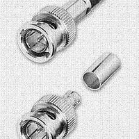
HP75BNC12X
Description
CONN BNC PLUG TRUE 75 OHM CRIMP
Manufacturer
Switchcraft Inc.
Series
BNCr
Type
BNCr
Datasheet
1.HP75BNC12X.pdf
(333 pages)
Specifications of HP75BNC12X
Impedance
75 Ohm
Rohs Information
Switchcraft RoHS Info.
Connector Style
BNC
Connector Type
Plug, Male Pins
Contact Termination
Crimp
Mounting Type
Free Hanging (In-Line)
Fastening Type
Bayonet Lock
Gender
M
Body Style
Straight
Terminate To
Coaxial Cable
Mounting Style
Cable
Termination
Crimp
Body Plating
Nickel
Contact Plating
Gold
Contact Material
Copper Alloy
Body Material
Copper Alloy
Product Length (mm)
25mm
Product
Connector
Rf Series
BNC
Polarity
Normal
Shell Plating
Nickel
Termination Style
Crimp
Cable Type
Belden 1417B, 1855A, 1865A, Gepco VDM230, VDM250, RGB230/250 Series, Comm/Scope 7537, 7538
Housing Material
Copper Alloy
Maximum Frequency
3 GHz
Lead Free Status / RoHS Status
Lead free / RoHS Compliant
Features
-
Frequency-max
-
Color
-
Cable Group
-
Lead Free Status / Rohs Status
Lead free / RoHS Compliant


64
w w w . s w i t c h c r a f t . c o m
CONNECTORS & RECEPTACLES
SLIM-LINE CONNECTORS
SLIM-LINE CONNECTORS
SL18 RECEPTACLES
Front of Panel Mount
SL MALE RECEPTACLES
SL FEMALE RECEPTACLES
SLIM-LINE CONNECTORS (continued)
Front of panel mount; 2 through 5 pins (male) or 2 through
5 contacts (female). Also 2-, 3- and 4-contact insert with
3 shunted (N.C.) contacts. Mounting locknut (Part Number
SL01), lockwasher (Part Number SL02), and flat washer
(Part Number SL03) supplied.
Part Number
Part Number
SL182M
SL183M
SL184M
SL185M
SL182F
SL183F
SL184F
SL185F
(17.7)
.696
Contacts
PANEL HOLE
Pins
2
3
4
5
2
3
4
5
Arrangements
SL183FS (typical)
Arrangements
DIMENSIONS ARE FOR REFERENCE ONLY
Contact
Pin
1
2
3
4
A
B
C
D
INSTALLING CABLE CLAMP ON INSERT
To install cable clamp on any insert:
1. Position insert approximately as shown in the diagram.
2. Hold clamp at approximately 30° angle (as shown). Place
3. Press center finger forward into slot and reduce angle of
Cable Clamp SL04
tip of clamp center finger into slot under molded ring “A”.
Note position of notch on insert in relation to slot.
clamp until clamp shoulders seat just ahead of molded
barrier on rear of insert “B”.
MOLDED
RING
“A”
INSERT
NOTCH
ON
(mm)
Note: Contact your Switchcraft Representative for price and delivery
Inch
PHONE: 773 792 - 2700
® Registered trademark of Switchcraft, Inc.
INSERT
“B”
CABLE
CLAMP
Related parts for HP75BNC12X
Image
Part Number
Description
Manufacturer
Datasheet
Request
R

Part Number:
Description:
CONN PLUG PHONE 1/4" 2POS RED
Manufacturer:
Switchcraft Inc.
Datasheet:

Part Number:
Description:
CONN PLUG 2-COND 1/4" PHONE SLD
Manufacturer:
Switchcraft Inc.
Datasheet:

Part Number:
Description:
CONN PLUG PHONE SILENT 2-COND
Manufacturer:
Switchcraft Inc.
Datasheet:

Part Number:
Description:
THICK PANEL/GOLD PLA
Manufacturer:
Switchcraft Inc.
Datasheet:

Part Number:
Description:
CONN JACK PHONE 1/4" 2POS CLOSED
Manufacturer:
Switchcraft Inc.
Datasheet:

Part Number:
Description:
CONN PHONE JACK 2COND 1/4" OPEN
Manufacturer:
Switchcraft Inc.
Datasheet:
Part Number:
Description:
CONN JACK PHONE 1/4" 2POS W/HDWR
Manufacturer:
Switchcraft Inc.
Datasheet:

Part Number:
Description:
CONN PLUG PHONE .206" 2POS BLACK
Manufacturer:
Switchcraft Inc.
Datasheet:
Part Number:
Description:
CONN PLUG PHONE 1/4" FLAT 2POS
Manufacturer:
Switchcraft Inc.
Datasheet:

Part Number:
Description:
CONN PLUG FLAT PHONE 1/4" 3-COND
Manufacturer:
Switchcraft Inc.
Datasheet:

Part Number:
Description:
PHONE T-JACK PANEL .25" STD SGL
Manufacturer:
Switchcraft Inc.
Datasheet:

Part Number:
Description:
CONN JACK PANEL 96POS W/O JACK
Manufacturer:
Switchcraft Inc.
Datasheet:
Part Number:
Description:
CONN PLUG PHONE .206" 3POS BLACK
Manufacturer:
Switchcraft Inc.
Datasheet:

Part Number:
Description:
CONN JACK 1/4" 3-COND IN-LINE
Manufacturer:
Switchcraft Inc.
Datasheet:

Part Number:
Description:
CONN PLUG AUDIO PHONE 3COND BLK
Manufacturer:
Switchcraft Inc.
Datasheet: