HP75BNC12X Switchcraft Inc., HP75BNC12X Datasheet - Page 47
HP75BNC12X
Manufacturer Part Number
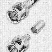
HP75BNC12X
Description
CONN BNC PLUG TRUE 75 OHM CRIMP
Manufacturer
Switchcraft Inc.
Series
BNCr
Type
BNCr
Datasheet
1.HP75BNC12X.pdf
(333 pages)
Specifications of HP75BNC12X
Impedance
75 Ohm
Rohs Information
Switchcraft RoHS Info.
Connector Style
BNC
Connector Type
Plug, Male Pins
Contact Termination
Crimp
Mounting Type
Free Hanging (In-Line)
Fastening Type
Bayonet Lock
Gender
M
Body Style
Straight
Terminate To
Coaxial Cable
Mounting Style
Cable
Termination
Crimp
Body Plating
Nickel
Contact Plating
Gold
Contact Material
Copper Alloy
Body Material
Copper Alloy
Product Length (mm)
25mm
Product
Connector
Rf Series
BNC
Polarity
Normal
Shell Plating
Nickel
Termination Style
Crimp
Cable Type
Belden 1417B, 1855A, 1865A, Gepco VDM230, VDM250, RGB230/250 Series, Comm/Scope 7537, 7538
Housing Material
Copper Alloy
Maximum Frequency
3 GHz
Lead Free Status / RoHS Status
Lead free / RoHS Compliant
Features
-
Frequency-max
-
Color
-
Cable Group
-
Lead Free Status / Rohs Status
Lead free / RoHS Compliant


42
w w w . s w i t c h c r a f t . c o m
CONNECTORS & RECEPTACLES
EN3 MINI WEATHERTIGHT CONNECTOR SERIES
EN3 MINI WEATHERTIGHT CONNECTOR SERIES
CRIMP CONTACT
INSERTION INSTRUCTIONS
CRIMP CONTACT
EXTRACTION INSTRUCTIONS
Note: Solder and PC contacts are factory assembled
CORD CONNECTOR ASSEMBLY INSTRUCTIONS
Cord Connector: To assemble the three-part cord connector, first feed the end of the cable through the boot, cable clamp
housing, and coupling ring in that order and position as shown in the figure below. NOTE: The coupling ring can also be
inserted onto the cord connector from the front. In-line Connector: Feed the end of the cable through the boot and cable
clamp housing in the order and position shown.
CABLE
Next, strip the cable .218" as shown and begin soldering conductors to pins, or insert contacts crimped on wire starting
with contact #1 next to the "notch" and following with the remaining conductors counter-clockwise with #6 or #8 conductor
in the center.
Push the cable clamp housing forward until it locks
into the connector body and snap the two clamps
into their compartments.
Finally, push the boot all the way forward to seat tightly
onto the cable clamp housing.
Remember: Cord connectors will not mate with each other. For cord-to-cord connection,
your customer must order a cord connector plus an in-line connector.
STEP 2
STEP 4
STEP 1
STEP 3
3/8"
MAX.
7/32"
™
™
BOOT
CABLE CLAMP
HOUSING
NOTCH (PIN #1
INDICATOR)
COUPLING
RING
CONTACT PINS
SOLDER
CORD
CONNECTOR
CORD
CONNECTOR
O-RING
(MOLDED ONTO
CORD CONNECTOR)
9/32"
DIMENSIONS ARE FOR REFERENCE ONLY
CABLE CLAMPS
CABLE
3/8"
MAX.
7/32"
CORD CONNECTOR
CRIMP TOOLS
NOTE: A positioner must be used with the
EN3CR and EN3CRAUTO.
BOOT
Part Number
EN3INS16
EN3INS20
EN3CR
EN3CRAUTO
EN3POS16
EN3POS20
Note: Contact your Switchcraft Representative for price and delivery
(mm)
Inch
CORD CONNECTOR
CABLE CLAMP
HOUSING
Tool Description
Insertion/Extraction Tool for 16 AWG
Insertion/Extraction Tool for 20 AWG
Crimp Hand Tool
Pneumatic Crimp Tool
Positioner for 16 AWG contacts and pins
Positioner for 20 AWG contacts and pins
CONTACT PINS
PHONE: 773 792 - 2700
NOTCH (PIN #1
INDICATOR)
CABLE CLAMPS
® Registered trademark of Switchcraft, Inc.
SOLDER
IN-LINE
CONNECTOR
IN-LINE CONNECTOR
IN-LINE CONNECTOR
IN-LINE
CONNECTOR
9/32"
Related parts for HP75BNC12X
Image
Part Number
Description
Manufacturer
Datasheet
Request
R

Part Number:
Description:
CONN PLUG PHONE 1/4" 2POS RED
Manufacturer:
Switchcraft Inc.
Datasheet:

Part Number:
Description:
CONN PLUG 2-COND 1/4" PHONE SLD
Manufacturer:
Switchcraft Inc.
Datasheet:

Part Number:
Description:
CONN PLUG PHONE SILENT 2-COND
Manufacturer:
Switchcraft Inc.
Datasheet:

Part Number:
Description:
THICK PANEL/GOLD PLA
Manufacturer:
Switchcraft Inc.
Datasheet:

Part Number:
Description:
CONN JACK PHONE 1/4" 2POS CLOSED
Manufacturer:
Switchcraft Inc.
Datasheet:

Part Number:
Description:
CONN PHONE JACK 2COND 1/4" OPEN
Manufacturer:
Switchcraft Inc.
Datasheet:
Part Number:
Description:
CONN JACK PHONE 1/4" 2POS W/HDWR
Manufacturer:
Switchcraft Inc.
Datasheet:

Part Number:
Description:
CONN PLUG PHONE .206" 2POS BLACK
Manufacturer:
Switchcraft Inc.
Datasheet:
Part Number:
Description:
CONN PLUG PHONE 1/4" FLAT 2POS
Manufacturer:
Switchcraft Inc.
Datasheet:

Part Number:
Description:
CONN PLUG FLAT PHONE 1/4" 3-COND
Manufacturer:
Switchcraft Inc.
Datasheet:

Part Number:
Description:
PHONE T-JACK PANEL .25" STD SGL
Manufacturer:
Switchcraft Inc.
Datasheet:

Part Number:
Description:
CONN JACK PANEL 96POS W/O JACK
Manufacturer:
Switchcraft Inc.
Datasheet:
Part Number:
Description:
CONN PLUG PHONE .206" 3POS BLACK
Manufacturer:
Switchcraft Inc.
Datasheet:

Part Number:
Description:
CONN JACK 1/4" 3-COND IN-LINE
Manufacturer:
Switchcraft Inc.
Datasheet:

Part Number:
Description:
CONN PLUG AUDIO PHONE 3COND BLK
Manufacturer:
Switchcraft Inc.
Datasheet: