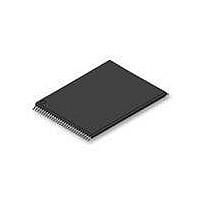
S29GL128P90TFIR10 Spansion Inc., S29GL128P90TFIR10 Datasheet - Page 36

S29GL128P90TFIR10
Manufacturer Part Number
S29GL128P90TFIR10
Description
IC, FLASH, 128MBIT, 90NS, TSOP-56
Manufacturer
Spansion Inc.
Datasheet
1.S29GL128P11TFI020.pdf
(80 pages)
Specifications of S29GL128P90TFIR10
Memory Type
Flash
Memory Size
128Mbit
Memory Configuration
16M X 8 / 8M X 16
Ic Interface Type
CFI, Parallel
Access Time
90ns
Supply Voltage Range
3.0 To 3.6 V
Memory Case Style
TSOP
Data Bus Width
8 bit, 16 bit
Architecture
Sectored
Interface Type
Serial
Supply Voltage (max)
3.6 V
Supply Voltage (min)
3 V
Maximum Operating Current
50 mA
Mounting Style
SMD/SMT
Operating Temperature
+ 85 C
Package / Case
TSOP-56
Lead Free Status / RoHS Status
Lead free / RoHS Compliant
Lead Free Status / RoHS Status
Lead free / RoHS Compliant, Lead free / RoHS Compliant
Available stocks
Company
Part Number
Manufacturer
Quantity
Price
Company:
Part Number:
S29GL128P90TFIR10
Manufacturer:
SPANSION
Quantity:
2 090
Part Number:
S29GL128P90TFIR10
Manufacturer:
SPANSION
Quantity:
20 000
Part Number:
S29GL128P90TFIR10D
Manufacturer:
SPANSION
Quantity:
20 000
7.8
36
7.8.1
Write Operation Status
DQ7: Data# Polling
The device provides several bits to determine the status of a program or erase operation. The following
subsections describe the function of DQ1, DQ2, DQ3, DQ5, DQ6, and DQ7.
The Data# Polling bit, DQ7, indicates to the host system whether an Embedded Program or Erase algorithm
is in progress or completed, or whether the device is in Erase Suspend. Data# Polling is valid after the rising
edge of the final WE# pulse in the command sequence. Note that the Data# Polling is valid only for the last
word being programmed in the write-buffer-page during Write Buffer Programming. Reading Data# Polling
status on any word other than the last word to be programmed in the write-buffer-page returns false status
information.
During the Embedded Program algorithm, the device outputs on DQ7 the complement of the datum
programmed to DQ7. This DQ7 status also applies to programming during Erase Suspend. When the
Embedded Program algorithm is complete, the device outputs the datum programmed to DQ7. The system
must provide the program address to read valid status information on DQ7. If a program address falls within a
protected sector, Data# polling on DQ7 is active, then that sector returns to the read mode.
During the Embedded Erase Algorithm, Data# polling produces a “0” on DQ7. When the Embedded Erase
algorithm is complete, or if the device enters the Erase Suspend mode, Data# Polling produces a “1” on DQ7.
The system must provide an address within any of the sectors selected for erasure to read valid status
information on DQ7.
After an erase command sequence is written, if all sectors selected for erasing are protected, Data# Polling
on DQ7 is active for approximately 100 µs, then the device returns to the read mode. If not all selected
sectors are protected, the Embedded Erase algorithm erases the unprotected sectors, and ignores the
selected sectors that are protected. However, if the system reads DQ7 at an address within a protected
sector, the status may not be valid.
Just prior to the completion of an Embedded Program or Erase operation, DQ7 may change asynchronously
with DQ6-DQ0 while Output Enable (OE#) is asserted low. That is, the device may change from providing
status information to valid data on DQ7. Depending on when the system samples the DQ7 output, it may read
Cycle
/* Example: Unlock Bypass Program Command
/* Do while in Unlock Bypass Entry Mode!
Cycle
/* Example: Unlock Bypass Exit Command */
1
2
*( (UINT16 *)base_addr ) = 0x00A0;
*( (UINT16 *)pa )
/* Poll until done or error.
/* If done and more to program, */
/* do above two cycles again.
1
2
*( (UINT16 *)base_addr ) = 0x0090;
*( (UINT16 *)base_addr ) = 0x0000;
Program Command
Program Setup
Description
Reset Cycle 1
Reset Cycle 2
Description
S29GL-P MirrorBit
(LLD Function = lld_UnlockBypassProgramCmd)
(LLD Function = lld_UnlockBypassResetCmd)
Table 7.15 Unlock Bypass Program
Operation
Table 7.16 Unlock Bypass Reset
*/
*/
Operation
= data;
Write
Write
Write
Write
/* write program setup command
D a t a
®
*/
*/
Flash Family
Program Address
/* write data to be programmed
Byte Address
Base + XXXh
Base + XXXh
Byte Address
Base + XXXh
S h e e t
Word Address
Base + XXXh
Base + XXXh
Program Address
S29GL-P_00_A12 November 20, 2009
Word Address
Base + XXXh
*/
*/
Program Data
0090h
0000h
Data
00A0h
Data


