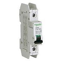
60118 SQUARE D, 60118 Datasheet - Page 35

60118
Manufacturer Part Number
60118
Description
MINIATURE CIRCUIT BREAKER 120V 1A
Manufacturer
SQUARE D
Series
Multi 9r
Datasheet
1.60949.pdf
(104 pages)
Specifications of 60118
Actuator Style
Toggle
No. Of Poles
1
Current Rating
1A
Voltage Rating Vac
240V
Mounting Type
DIN Rail
Rohs Compliant
Yes
Available stocks
Company
Part Number
Manufacturer
Quantity
Price
Company:
Part Number:
60118-1
Manufacturer:
TE/AMP
Quantity:
30 000
Company:
Part Number:
60118-1
Manufacturer:
TE
Quantity:
90 000
Company:
Part Number:
60118-1
Manufacturer:
TE
Quantity:
35 000
© 2002–2010 Schneider Electric
All Rights Reserved
IEC Rated ID Residual Current Switches
The ID Residual Current Switches provide ground fault protection for electrical circuits, as well as the
functions of isolation and switching. ID switches have an electromechanical release that opens a circuit
automatically in the case of a fault between phase and earth greater than 10, 30, or 300 mA,
depending on the model. The switch operates without the need for an auxiliary source of power. A
version with time delay (selective) provides non-adjustable time delay for coordination with
downstream instantaneous residual current devices. The ID Switch is available in 2 pole (1 phase) and
4 pole (3 phase) versions.
The ground fault is displayed on the front face by a red mechanical indicator.
NOTE: The ID residual current switch has only one protective function—detection of earth leakage
current. There is no thermal or magnetic overcurrent protection. Therefore, the circuit must be
protected by an upstream circuit breaker or supplementary protector. For combined overcurrent and
residual current protection, an alternative is a C60 circuit breaker equipped with an auxiliary Vigi
ground-fault detector module.
The ID device can also be manually operated as a switch. Remote monitoring and control can be
provided with optional C60 accessories including the OF Auxiliary Switch, SD Alarm Switch, MN
Undervoltage Release, and/or MX + OF Shunt Trip.
NOTE: All of these auxiliaries require the use of the OFS Auxiliary Switch (Cat. No. 26923) to adapt to
the ID Residual Current Switch.
A test button provided on the front of the ID Residual Current Switch to allow periodic testing of the
device.
Figure 8:
Table 33:
Voltage
Connection, Box Lug
Sensitivities
Time/Current Curve
Level of Immunity
Operating Temperature
Tropicalization
Mounting
Number of Operating Cycles Electrical (O-C)
See Table 29 for weights, dimensions and interrupting ratings
IEC Rated ID Residual Current Switches
Specifications for IEC Rated ID Residual Current Switches
35 mm DIN Rail
Nominal Voltage
High Voltage Withstand
14–2 AWG (2.5–35 mm
Cu Wire Only
1 AWG (50 mm
Fixed at 10, 30, or 300 mA
Instantaneous or Selective Release S (Time Delay)
250 A Peak
-5 to 60°C (22 to 140°F)
Treatment 2
2
) Solid Cables, Cu Wire Only Torque to 31 lb-in (3.5 N•m)
2
) Stranded Cables,
Section 4—Ground-Fault Protection Devices
Torque to 31 lb-in (3.5 N•m)
According to 8/20 ms Periodical Wave
Relative Humidity: 95% at 55°C (131°F) per IEC 68-2-30
20,000
240 to 415 Vac, +10%, -20%, 50/60 Hz
6 kV
Multi 9™ System Catalog
07/2010
™
35


