60118 SQUARE D, 60118 Datasheet - Page 47
60118
Manufacturer Part Number
60118
Description
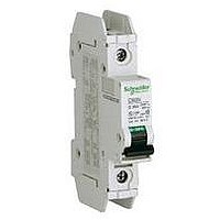
MINIATURE CIRCUIT BREAKER 120V 1A
Manufacturer
SQUARE D
Series
Multi 9r
Datasheet
1.60949.pdf
(104 pages)
Specifications of 60118
Actuator Style
Toggle
No. Of Poles
1
Current Rating
1A
Voltage Rating Vac
240V
Mounting Type
DIN Rail
Rohs Compliant
Yes
Available stocks
Company
Part Number
Manufacturer
Quantity
Price
Company:

Part Number:
60118-1
Manufacturer:
TE/AMP
Quantity:
30 000
Company:
Part Number:
60118-1
Manufacturer:
TE
Quantity:
90 000
Company:
Part Number:
60118-1
Manufacturer:
TE
Quantity:
35 000


© 2002–2010 Schneider Electric
All Rights Reserved
Voltage
277 Vac
< 240 Vac
130 Vac
< 48 Vdc
< 24 Vdc
Breaking
Capacity
(A)
SD
3
6
1
2
6
OF
3
6
1
2
6
OF Auxiliary Switch
The OF Auxiliary Switch communicates the OPEN or CLOSED status of the associated C60 circuit
breaker or supplementary protector via auxiliary contacts. It is mechanically linked to the
supplementary protector (See the SD Alarm Switch for TRIP status).
It may be used in conjunction with the SD Alarm Switch, which presents the trip status, and the MN
Undervoltage Release. It would not normally be used with the MX + OF Shunt Trip because that device
already includes the OF function.
•
•
OFS Auxiliary Switch and Adapter (for GFP and ID RCD)
The OFS Auxiliary Switch and Adapter has an auxiliary switch to provide the auxiliary switch function
and an adapter which allows the UL Listed GFP ground fault protector and the IEC Rated ID Residual
Current Switches (in Section 4) to use the same electrical accessories as the C60 supplementary
protectors, including the OF Auxiliary Switch, SD Alarm Switch, MN Undervoltage Release, and/or MX
+ OF Shunt Trip. It may be used alone or with accessories.
IEC Rated; not UL/CSA Recognized
Table 43:
SD Alarm Switch
The SD Alarm Switch communicates the trip status of the associated C60 or C120 circuit breakers or
supplementary protectors via auxiliary contacts. It is mechanically linked to the protective device.
Locally, it also indicates a tripped-on-fault condition of the protective device with a red indicator flag on
the front panel. (Use the OF Auxiliary Switch for open or closed status.)
A test switch allows simulation of the SD function without operating the protective device.
The SD Alarm Switch is reset when the associated protective device is reset, or it may by reset
independently of the protective device with a reset lever on its front panel.
The SD Alarm Switch may show the circuit breaker status, using V Type Signal Lamps, other
annunciators, or a control system. It may be used in conjunction with the OF Auxiliary Switch which
presents the open or closed status, the MN Undervoltage Release, and/or the MX + OF Shunt Trip.
•
•
Figure 15:
Description
OFS Auxiliary Switch and Adapter
14 12 C2
MX + OF Shunt Trip
UL Recognized for use with UL 1077 Recognized devices and UL 489/CSA C22.2 No.5 Listed devices.
CSA and IEC Rated.
UL Recognized for use with UL 1077 Recognized devices and UL Listed for use with UL 489/CSA
C22.2 No.5 Listed devices.
CSA and IEC Rated
U >
C1
Catalog Number for OFS Auxiliary Switch and Adapter
Electrical Auxiliary Schematics
D1
MN Undervoltage Release
Width in Modules
U <
D2
1
Catalog Number
OF Auxiliary Switch
14 12 11
26923
Multi 9™ System Catalog
Section 5—Accessories
SD Alarm Switch
94 92 91
07/2010
47
Related parts for 60118
Image
Part Number
Description
Manufacturer
Datasheet
Request
R


Part Number:
Description:
Pushbutton, Non-Illum'd Red "STOP", Momentary, 1NO-1NC, Square 30mm, 10A, 600V
Manufacturer:
SQUARE D
Datasheet:

Part Number:
Description:
KITS,TWIDO? PROGRAMMABLE CONTROLLERS,KITS,TWIDOPACK STARTER KIT - ADVANCED LEVEL,PROGRAMMABLE CONTROLLERS,TWIDO? PROGRAMMABLE CONTROLLERS ,SQUARE D
Manufacturer:
SQUARE D

Part Number:
Description:
LAMPS,INDICATOR,STACKABLE,LAMPS, STACKABLE INDICATOR,VISUAL INDICATING SIGNALS,XVB SERIES INDICATING BANKS ,SQUARE D
Manufacturer:
SQUARE D
Part Number:
Description:
LAMPS,INDICATOR,STACKABLE,LAMPS, STACKABLE INDICATOR,VISUAL INDICATING SIGNALS,XVB SERIES INDICATING BANKS ,SQUARE D
Manufacturer:
SQUARE D
Datasheet:
Part Number:
Description:
I/O EXTENDER MODULE 4 D IN & 2 D OUTPUT
Manufacturer:
SQUARE D
Datasheet:
Part Number:
Description:
CB ACCESSORY, UNDERVOLTAGE TRIP 48V DC
Manufacturer:
SQUARE D
Datasheet: