60118 SQUARE D, 60118 Datasheet - Page 85
60118
Manufacturer Part Number
60118
Description
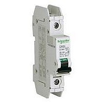
MINIATURE CIRCUIT BREAKER 120V 1A
Manufacturer
SQUARE D
Series
Multi 9r
Datasheet
1.60949.pdf
(104 pages)
Specifications of 60118
Actuator Style
Toggle
No. Of Poles
1
Current Rating
1A
Voltage Rating Vac
240V
Mounting Type
DIN Rail
Rohs Compliant
Yes
Available stocks
Company
Part Number
Manufacturer
Quantity
Price
Company:

Part Number:
60118-1
Manufacturer:
TE/AMP
Quantity:
30 000
Company:
Part Number:
60118-1
Manufacturer:
TE
Quantity:
90 000
Company:
Part Number:
60118-1
Manufacturer:
TE
Quantity:
35 000


© 2002–2010 Schneider Electric
All Rights Reserved
Typical IEC Grounding Systems
All electrical installations complying with safety standards and regulations are grounded in order to
protect people and equipment. The term “grounding system” standardizes the grounding method used
in the installation. The grounding system runs:
•
•
The IEC 364 (Section 3) Standard defines three types of grounding systems: TT, IT and TN-C or TN-S.
Codification of the Grounding Systems
Grounding systems are referred to by two or three letters
•
•
•
The TT Grounded Neutral System
This “directly-grounded neutral” system is the easiest to install, monitor and use. Main features are:
•
•
•
System characteristics upon installation:
•
•
•
Figure 64:
First, from the neutral of the secondary side of the transformer,
Next, from the installation frames.
1st letter—Status of the neutral of the transformer or source:
— I: Ungrounded
— T: Grounded
2nd letter—Status of the electrical frames of the loads:
— T: Grounded
— N: Connected to neutral
3rd letter—Status of the neutral (N) and the protective conductor (PE):
— S: N and PE are separate
— C: N and PE are in the same conductor (PEN)
The neutral point of the distribution transformer is directly grounded.
The installation frames are connected to several ground connections by the PE protective
conductor.
The frame and neutral ground connections are separate.
Tripping is compulsory on the first fault.
Thus, at least one RCD is necessary at the incoming end of the installation.
If the load frames are not all connected to the same grounding connection, one RCD must be
installed for each set of equipment.
TT Grounding System with Residual Current
Device (RCD) at the Incoming End of the Installation
RCD
TT Grounding Systems
PE
1
2
3
N
TT Grounding System with One Residual
Current Device (RCD) for Each Set of Equipment
T N S
RCD
Multi 9™ System Catalog
for example:
PE
Section 8—Applications
RCD
PE
07/2010
RCD
1
2
3
N
85
Related parts for 60118
Image
Part Number
Description
Manufacturer
Datasheet
Request
R


Part Number:
Description:
Pushbutton, Non-Illum'd Red "STOP", Momentary, 1NO-1NC, Square 30mm, 10A, 600V
Manufacturer:
SQUARE D
Datasheet:

Part Number:
Description:
KITS,TWIDO? PROGRAMMABLE CONTROLLERS,KITS,TWIDOPACK STARTER KIT - ADVANCED LEVEL,PROGRAMMABLE CONTROLLERS,TWIDO? PROGRAMMABLE CONTROLLERS ,SQUARE D
Manufacturer:
SQUARE D

Part Number:
Description:
LAMPS,INDICATOR,STACKABLE,LAMPS, STACKABLE INDICATOR,VISUAL INDICATING SIGNALS,XVB SERIES INDICATING BANKS ,SQUARE D
Manufacturer:
SQUARE D
Part Number:
Description:
LAMPS,INDICATOR,STACKABLE,LAMPS, STACKABLE INDICATOR,VISUAL INDICATING SIGNALS,XVB SERIES INDICATING BANKS ,SQUARE D
Manufacturer:
SQUARE D
Datasheet:
Part Number:
Description:
I/O EXTENDER MODULE 4 D IN & 2 D OUTPUT
Manufacturer:
SQUARE D
Datasheet:
Part Number:
Description:
CB ACCESSORY, UNDERVOLTAGE TRIP 48V DC
Manufacturer:
SQUARE D
Datasheet: