SX-550-1701 Silex Technology, SX-550-1701 Datasheet - Page 66
SX-550-1701
Manufacturer Part Number
SX-550-1701
Description
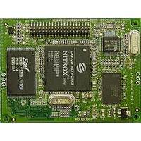
WiFi / 802.11 Modules & Development Tools 802.11a/b/g Bridge Serial Server
Manufacturer
Silex Technology
Datasheet
1.SX-550-6900.pdf
(122 pages)
Specifications of SX-550-1701
Interface Type
UART
Board Size
59.6 mm x 49.1 mm x 14.3 mm
Security
802.1xEAP, PEAP, WEP, WPAPSK, TKIP, WPA2, AES
Operating Voltage
3.3 VDC
Operating Temperature Range
0 C to + 50 C
Lead Free Status / RoHS Status
Lead free / RoHS Compliant


Part Number 40183-101
Example:
SET GPIO DIRM <bit-mask>
SHOW GPIO DIRM <bit-mask>
SET GPIO SPECIAL [EN | DIS]
SHOW GPIO SPECIAL
GPIO # = {1|2|3|4|5|6|7|8}
Local> set gpio dirm 01
Local> show gpio dirm
GPIO direction mask=01
Sets all direction control bits, where <bit-mask> is an 8 bit
mask expressed as 2 hex digits. This value should be in the
range 00-FF. The mask is encoded as follows:
GPIO10 GPIO9 GPIO6 GPIO5 GPIO4 GPIO3 GPIO2 GPIO1
A value of 1 sets the corresponding GPIO line to be an
output. A value of 0 sets the GPIO line to be an input. For
example, a hex value of 80 sets GPIO8 as an output, all other
GPIO signals are input.
NOTE: The direction bit configuration is not changed by a
configuration reset to default.
Shows all direction control bits
Sets a single special function control bit. This command
enables or disables the special function of the GPIO signal
specified. <gpio-num> must be in the range of 1-10. The
special functions are as follows:
GPIO_1
GPIO_2
GPIO_3
GPIO_4
GPIO_5
GPIO_6
GPIO_9
GPIO_10
NOTE: GPIO_7 is dedicated for use with a test/reset
pushbutton switch, while GPIO_8 is dedicated for a power
status LED. The special function bit configuration is not
changed by a configuration reset to default.
Shows the current setting of the GPIO special function
configuration (note that GPIO #7 in this display is actually
GPIO_9, while GPIO #8 is actually GPIO_10).
7
Silex SX-550 Developer's Guide
6
DSR0 (Serial Port 1 DTR output)
DTR0 (Serial Port 1 DSR input)
DCD0 (Serial Port 1 DCD input)
DTR1 (Serial Port 2 DTR output)
DSR1 (Serial Port 2 DSR input)
DCD1 (Serial Port 2 DCD input)
D2 YELLOW (network status LED)
D3 GREEN (network status LED)
5
4
3
2
1
0
Page 58
Related parts for SX-550-1701
Image
Part Number
Description
Manufacturer
Datasheet
Request
R

Part Number:
Description:
WiFi / 802.11 Modules & Development Tools SS Developers Kit need buy sx-550-1701
Manufacturer:
Silex Technology
Datasheet:

Part Number:
Description:
WiFi / 802.11 Modules & Development Tools 802.11a/b/g Bridge Serial Server
Manufacturer:
Silex Technology
Datasheet:
Part Number:
Description:
WiFi / 802.11 Modules & Development Tools Wired Internal OEM 10/100 Serial Server
Manufacturer:
Silex Technology
Datasheet:

Part Number:
Description:
WiFi / 802.11 Modules & Development Tools Internal OEM SDIO Atheros Crd802.11abg
Manufacturer:
Silex Technology
Datasheet:
Part Number:
Description:
WiFi / 802.11 Development Tools Eval Kit for SX-570/SX-580
Manufacturer:
Silex Technology
Datasheet:

Part Number:
Description:
Networking Modules & Development Tools 10/100 USB Device Server
Manufacturer:
Silex Technology
Datasheet:

Part Number:
Description:
Networking Modules & Development Tools 802.11 b/g Wireless USB Device Server
Manufacturer:
Silex Technology
Datasheet:
Part Number:
Description:
WiFi / 802.11 Modules 802.11a/b/g/n USB dev server, 2 ports
Manufacturer:
Silex Technology
Datasheet:

Part Number:
Description:
WiFi / 802.11 Modules & Development Tools AR6002 Radio Evaluation Kit
Manufacturer:
Silex Technology
Datasheet:
Part Number:
Description:
WiFi / 802.11 Modules & Development Tools 802.11abg SDIO Card Open Source Drivers
Manufacturer:
Silex Technology
Datasheet:
Part Number:
Description:
WiFi / 802.11 Modules WiFi SDIO Radio Card w/cable and antenna
Manufacturer:
Silex Technology
Datasheet:
Part Number:
Description:
WiFi / 802.11 Modules 802.11a/b/g/n USB dev server, 2 ports
Manufacturer:
Silex Technology
Datasheet:
Part Number:
Description:
WiFi / 802.11 Modules WiFi SDIO Radio Card
Manufacturer:
Silex Technology
Datasheet:
Part Number:
Description:
WiFi / 802.11 Modules 802.11a/b/g/n Mini PCI card, 3x3MIMO
Manufacturer:
Silex Technology
Datasheet:
Part Number:
Description:
WiFi / 802.11 Modules 802.11b/g SDIO Surfa ce Mount Mod Sample
Manufacturer:
Silex Technology
Datasheet: