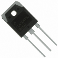
FGA50N100BNTD2 Fairchild Semiconductor, FGA50N100BNTD2 Datasheet

FGA50N100BNTD2
Specifications of FGA50N100BNTD2
Available stocks
Related parts for FGA50N100BNTD2
FGA50N100BNTD2 Summary of contents
Page 1
... R (DIODE) Thermal Resistance, Junction to Case θJC R Thermal Resistance, Junction to Ambient θJA ©2009 Fairchild Semiconductor Corporation FGA50N100BNTD2 Rev. A General Description Trench insulated gate bipolar transistors (IGBTs) with NPT = 2 60A technology show outstanding performance in conduction and C switching characteristics as well as enhanced avalanche ruggedness. These devices are well suited for micro-wave, Induction heating (I-H) Jar, induction heater, home appliance ...
Page 2
... Gate to Emitter Charge ge Q Gate to Collector Charge gc Electrical Characteristics of the Diode V Diode Forward Voltage FM t Diode Reverse Recovery Time rr I Instantaneous Reverse Current R FGA50N100BNTD2 Rev. A Packaging Package Type Qty per Tube TO-3PN Rail / Tube T = 25°C unless otherwise noted C Test Conditions = 0V 1mA GE C ...
Page 3
... 125 C C 120 Collector-Emitter Voltage, V Figure 5. Saturation Voltage vs. Case Temperature at Variant Current Level 4.5 Common Emitter V = 15V GE 3.0 1.5 1 Collector-EmitterCase Temperature, T FGA50N100BNTD2 Rev. A Figure 2. Typical Output Characteristics 200 160 9V 120 [V] CE Figure 4. Transfer Characteristics 200 160 120 [V] CE Figure 6. Saturation Voltage vs. V ...
Page 4
... Figure 9. Capacitance Characteristics 8000 6000 C ies 4000 2000 C C res oes 0 1 Collector-Emitter Voltage, V Figure 11. SOA Characteristics 500 100 10 1 *Notes: 0 150 Single Pulse 0. 100 Collector-Emitter Voltage, V FGA50N100BNTD2 Rev. A Figure 8. Saturation Voltage vs Common Emitter [V] GE Figure 10. Gate charge Characteristics 15 12 Common Emitter 0V 1MHz ...
Page 5
... Collector Current 200 100 Collector Current, I Figure 17. Switching Loss vs. Gate Resistance 50 Common Emitter V = 600V 15V 60A 125 Gate Resistance, R FGA50N100BNTD2 Rev. A Figure 14. Turn-off Characteristics vs. 2000 1000 100 = 600V 15V 60A 125 Ω Figure 16. Turn-off Characteristics vs. 1000 100 d(on) Common Emitter Ω 15V ...
Page 6
... Figure 21. Reverse Current 300 100 125 0.1 0. 1E-3 50 200 400 600 Reverse Voltage, V Figure 23. Reverse Recovery Characteristics vs. Forward Current Forward Current,I FGA50N100BNTD2 Rev. A Figure 20. Forward Characteristics 200 100 10 1 0.1 1000 3000 [V] CE Figure 22. Reverse Recovery Characteristics vs 800 1000 [ µ di/dt = 100A/ ...
Page 7
... Typical Performance Characteristics 1 0.1 0.01 1E-3 1E-5 FGA50N100BNTD2 Rev. A Figure 24.Transient Thermal Impedance of IGBT 0.5 0.2 0.1 0.05 0.02 0.01 single pulse 1E-4 1E-3 0.01 Rectangular Pulse Duration [sec Duty Factor t1/t2 Peak T = Pdm x Zthjc + 0 www.fairchildsemi.com ...
Page 8
... Mechanical Dimensions FGA50N100BNTD2 Rev. A TO-3PN 8 www.fairchildsemi.com ...
Page 9
... Definition of Terms Datasheet Identification Product Status Advance Information Formative / In Design Preliminary First Production No Identification Needed Full Production Obsolete Not In Production FGA50N100BNTD2 Rev. A ® FRFET Programmable Active Droop™ SM ® Global Power Resource QFET Green FPS™ QS™ Green FPS™ e-Series™ ...


