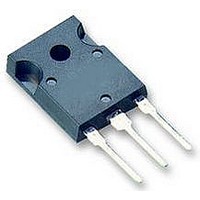
IKW15N120T2 Infineon Technologies, IKW15N120T2 Datasheet - Page 11

IKW15N120T2
Manufacturer Part Number
IKW15N120T2
Description
IGBT 1200V 30A 235W TO247-3
Manufacturer
Infineon Technologies
Series
TrenchStop™r
Datasheet
1.IKW15N120T2.pdf
(15 pages)
Specifications of IKW15N120T2
Igbt Type
Trench
Voltage - Collector Emitter Breakdown (max)
1200V
Vce(on) (max) @ Vge, Ic
2.2V @ 15V, 15A
Current - Collector (ic) (max)
30A
Power - Max
235W
Input Type
Standard
Mounting Type
Through Hole
Package / Case
TO-247-3 (Straight Leads)
Transistor Type
IGBT
Dc Collector Current
15A
Collector Emitter Voltage Vces
2.2V
Power Dissipation Max
235W
Collector Emitter Voltage V(br)ceo
1.2kV
Operating Temperature Range
-40°C To +175°C
Transistor Case Style
TO-247
Rohs Compliant
Yes
Switching Frequency
TRENCHSTOP2 2-20kHz
Package
TO-247
Vce (max)
1,200.0 V
Ic(max) @ 25°
30.0 A
Ic(max) @ 100°
15.0 A
Lead Free Status / RoHS Status
Lead free / RoHS Compliant
Available stocks
Company
Part Number
Manufacturer
Quantity
Price
Company:
Part Number:
IKW15N120T2
Manufacturer:
INFINEON
Quantity:
240
Company:
Part Number:
IKW15N120T2
Manufacturer:
INFINEON
Quantity:
12 500
Part Number:
IKW15N120T2
Manufacturer:
INFINEON/英飞凌
Quantity:
20 000
Part Number:
IKW15N120T2 K15T1202
Manufacturer:
INFINEON/英飞凌
Quantity:
20 000
Company:
Part Number:
IKW15N120T2FKSA1
Manufacturer:
INFINEON
Quantity:
1 001
Power Semiconductors
20A
15A
10A
Figure 23. Typical reverse recovery time as
Figure 25. Typical reverse recovery current
5A
0A
600ns
500ns
400ns
300ns
200ns
100ns
0ns
di
di
400A/µs
a function of diode current slope
(V
Dynamic test circuit in Figure E)
as a function of diode current
slope
(V
Dynamic test circuit in Figure E)
F
F
/dt,
/dt,
R
R
=600V, I
=600V, I
400A/µs
DIODE CURRENT SLOPE
DIODE CURRENT SLOPE
F
F
=15A,
=15A,
800A/µs
800A/µs
T
J
=175°C
T
J
T
=25°C
1200A/µs
T
J
=175°C
1200A/µs
J
=25°C
TrenchStop
11
Figure 24. Typical reverse recovery charge
Figure 26. Typical diode peak rate of fall of
3µC
2µC
1µC
0µC
-600A/µs
-500A/µs
-400A/µs
-300A/µs
-200A/µs
-100A/µs
®
-0A/µs
2
nd
generation Series
di
di
as a function of diode current
slope
(V
Dynamic test circuit in Figure E)
reverse recovery current as a
function of diode current slope
(V
Dynamic test circuit in Figure E)
400A/µs
F
F
/dt,
R
/dt,
R
=600V, I
=600V, I
400A/µs
DIODE CURRENT SLOPE
DIODE CURRENT SLOPE
IKW15N120T2
F
F
=15A,
=15A,
800A/µs
800A/µs
T
Rev. 2.1
J
=25°C
T
J
T
=175°C
J
=25°C
1200A/µs
T
J
1200A/µs
=175°C
Sep 08


