SGR20N40LTF Fairchild Semiconductor, SGR20N40LTF Datasheet
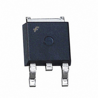
IGBT TRENCH 400V 150A DPAK

SGR20N40LTF

Manufacturer Part Number
SGR20N40LTF
Description
IGBT TRENCH 400V 150A DPAK
Manufacturer
Fairchild Semiconductor
Datasheet

Specifications of SGR20N40LTF

Igbt Type
Trench
Voltage - Collector Emitter Breakdown (max)
400V
Vce(on) (max) @ Vge, Ic
8V @ 4.5V, 150A
Power - Max
45W
Input Type
Standard
Mounting Type
Surface Mount
Package / Case
DPak, TO-252 (2 leads+tab), SC-63
Lead Free Status / RoHS Status
Lead free / RoHS Compliant
Current - Collector (ic) (max)
-
©2001 Fairchild Semiconductor Corporation
SGR20N40L / SGU20N40L
General Description
Insulated Gate Bipolar Transistors (IGBTs) with a trench
gate structure provide superior conduction and switching
performance in comparison with transistors having a planar
gate structure. They also have wide noise immunity. These
devices are very suitable for strobe applications
Application
Strobe flash.
Absolute Maximum Ratings
Notes :
(1) Repetitive rating : Pulse width limited by max. junction temperature
Thermal Characteristics
Notes :
(2) Mounted on 1” square PCB (FR4 or G-10 Material)
V
V
I
P
T
T
T
R
R
R
CM (1)
stg
J
L
CES
GES
C
Symbol
JC
JA
JA
Symbol
(D-PAK)
(I-PAK)
Collector - Emitter Voltage
Gate - Emitter Voltage
Pulsed Collector Current
Maximum Power Dissipation
Operating Junction Temperature
Storage Temperature Range
Maximum Lead Temp. for soldering
purposes, 1/8” from case for 5 seconds
G E
Thermal Resistance, Junction-to-Case
Thermal Resistance, Junction-to-Ambient (PCB Mount)
Thermal Resistance, Junction-to-Ambient
D-PAK
C
Description
Parameter
G
T
C
C
E
= 25 C unless otherwise noted
I-PAK
@ T
C
Features
• High input impedance
• High peak current capability (150A)
• Easy gate drive
• Surface Mount : SGR20N40L
• Straight Lead : SGU20N40L
= 25 C
(2)
SGR / SGU20N40L
Typ.
--
--
--
G
G
-40 to +150
-40 to +150
400
150
300
45
6
C
C
Max.
E
E
110
3.0
50
SGR20N40L / SGU20N40L Rev. A1
IGBT
August 2001
Units
Units
C/W
C/W
C/W
W
V
V
A
C
C
C

Related parts for SGR20N40LTF

SGR20N40LTF Summary of contents

Page 1

... JA R (I-PAK) Thermal Resistance, Junction-to-Ambient JA Notes : (2) Mounted on 1” square PCB (FR4 or G-10 Material) ©2001 Fairchild Semiconductor Corporation Features • High input impedance • High peak current capability (150A) • Easy gate drive • Surface Mount : SGR20N40L • Straight Lead : SGU20N40L ...

Page 2

... Input Capacitance ies C Output Capacitance oes C Reverse Transfer Capacitance res Switching Characteristics t Turn-On Delay Time d(on) t Rise Time r t Turn-Off Delay Time d(off) t Fall Time f * Notes : Recommendation of R Value : ©2001 Fairchild Semiconductor Corporation unless otherwise noted C Test Conditions Min 0V 1mA 450 CES ...

Page 3

... Gate-Emitter Voltage, V Fig 3. Saturation Voltage vs Common Emitter T = 125℃ 70A Gate-Emitter Voltage, V Fig 5. Saturation Voltage vs. V ©2001 Fairchild Semiconductor Corporation 7 Common Emitter 5. 4.0V 3. -50 [V] CE Fig 2. Saturation Voltage vs. Case Temperature at Variant Current Level 20 Common Emitter T = 25℃ ...

Page 4

... Common Emitter V = 300V 2Ω 25℃ Gate-Charge Fig 7. Turn-On Characteristics vs. Gate Resistance ©2001 Fairchild Semiconductor Corporation 200 175 150 125 100 [nC] Fig 8. Collector Current Limit vs Gate - Emitter Voltage, V [V] GE Gate - Emitter Voltage Limit SGR20N40L / SGU20N40L Rev ...

Page 5

... TRADEMARKS The following are registered and unregistered trademarks Fairchild Semiconductor owns or is authorized to use and is not intended exhaustive list of all such trademarks. A CEx™ FAST Bottomless™ FASTr™ FRFET™ CoolFET™ GlobalOptoisolator™ CROSSVOLT™ GTO™ DenseTrench™ ...

Related keywords