U1898_D27Z Fairchild Semiconductor, U1898_D27Z Datasheet

TRANS SW N-CH 40V 50MA TO-92

U1898_D27Z

Manufacturer Part Number
U1898_D27Z
Description
TRANS SW N-CH 40V 50MA TO-92
Manufacturer
Fairchild Semiconductor
Datasheet

Specifications of U1898_D27Z

Current - Drain (idss) @ Vds (vgs=0)
15mA @ 20V
Fet Type
N-Channel
Voltage - Breakdown (v(br)gss)
40V
Voltage - Cutoff (vgs Off) @ Id
2V @ 1nA
Input Capacitance (ciss) @ Vds
16pF @ 20V
Resistance - Rds(on)
50 Ohm
Mounting Type
Through Hole
Package / Case
TO-92-3 (Standard Body), TO-226
Power - Max
625mW
Lead Free Status / RoHS Status
Lead free / RoHS Compliant
©2004 Fairchild Semiconductor Corporation
N-Channel Switch
• This device is designed for low level analog switching, sample and
• Sourced from Process 51.
• See J111 for characteristics.
Absolute Maximum Ratings*
* This ratings are limiting values above which the serviceability of any semiconductor device may be impaired.
NOTES:
1) These rating are based on a maximum junction temperature of 150 degrees C.
2) These are steady limits. The factory should be consulted on applications involving pulsed or low duty cycle operations.
Electrical Characteristics
* Pulse Test: Pulse Width
Thermal Characteristics
V
V
I
T
Off Characteristics
V
V
I
On Characteristics
I
r
Small Signal Characteristics
r
C
C
Switching Characteristics
t
t
P
R
R
GF
DGO
DSS
on
off
DS(on)
ds(on)
hold circuits and chopper stabalized amplifiers.
Symbol
J
DG
GS
(BR)GS
GS(off)
D
iss
rss
Symbol
, T
JC
JA
Symbol
STG
Gate-Source Breakdown Voltage
Gate-Source Cutoff Voltage
Drain-Gate Leakage Current
Zero-Gate Voltage Drain Current *
Drain-Source On Resistance
Input Capacitance
Reverse Transfer Capacitance
Turn-On Time
Turn-Off Time
Total Device Dissipation
Derate above 25 C
Thermal Resistance, Junction to Case
Thermal Resistance, Junction to Ambient
Drain-Gate Voltage
Gate-Source Voltage
Forward Gate Current
Operating and Storage Junction Temperature Range
300 s, Duty Cycle
Parameter
2.0%
Parameter
T
a
T
=25 C unless otherwise noted
a
=25 C unless otherwise noted
Parameter
T
a
=25 C unless otherwise noted
U1898
I
V
V
V
I
V
V
V
I
V
G
D
D(on)
DS
DG
DS
DS
DS
GS
GS(off)
= 1.0 A, V
= 1.0 mA, V
= 20 V, I
= 20 V, V
= VGS = 0, f= 1.0 kHz
= 20, V
= - 20 V, f = 1.0 MHz
= 20 V, I
= 6.0 mA
= 6.0 V
Test Condition
GS
D
S
GS
DS
= 1.0 nA
= 0
GS
= 0, f = 1.0 MHz
= 0
= 0
= 0
Max.
625
125
357
5.0
1. Drain 2. Source 3. Gate
1
-55 ~ 150
Ratings
-40
40
50
Min.
-2.0
-40
15
TO-92
Max.
-200
-7.0
5.0
50
50
16
35
60
mW/ C
Units
mW
C/W
C/W
Units
mA
Rev. A, April 2004
V
V
C
Units
mA
pA
pF
pF
ns
ns
V
V

Related parts for U1898_D27Z

U1898_D27Z Summary of contents

Page 1

... Pulse Test: Pulse Width 300 s, Duty Cycle Thermal Characteristics Symbol P Total Device Dissipation D Derate above Thermal Resistance, Junction to Case JC R Thermal Resistance, Junction to Ambient JA ©2004 Fairchild Semiconductor Corporation U1898 T =25 C unless otherwise noted a Parameter T =25 C unless otherwise noted a Test Condition ...

Page 2

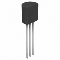
... Package Dimensions 0.46 0.10 1.27TYP [1.27 ] 0.20 ©2004 Fairchild Semiconductor Corporation TO-92 +0.25 4.58 –0.15 1.27TYP [1.27 ] 0.20 3.60 0.20 (R2.29) +0.10 0.38 –0.05 Dimensions in Millimeters Rev. A, April 2004 ...

Page 3

... TRADEMARKS The following are registered and unregistered trademarks Fairchild Semiconductor owns or is authorized to use and is not intended exhaustive list of all such trademarks. ACEx™ FACT Quiet Series™ ® ActiveArray™ FAST Bottomless™ FASTr™ CoolFET™ FPS™ CROSSVOLT™ ...

Related keywords