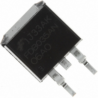
FDB035AN06A0 Fairchild Semiconductor, FDB035AN06A0 Datasheet

FDB035AN06A0
Specifications of FDB035AN06A0
FDB035AN06A0TR
Available stocks
Related parts for FDB035AN06A0
FDB035AN06A0 Summary of contents
Page 1
... Distributed Power Architectures and VRMs • Primary Switch for 12V and 24V systems DRAIN (FLANGE 25°C unless otherwise noted C Parameter 10V 10V, with C/ copper pad area December 2010 Ratings Units Figure 4 A 625 mJ 310 -55 to 175 C o 0. C/W FDB035AN06A0 Rev. A2 ...
Page 2
... I = 80A 10V 2 80A 40A 75A, dI /dt = 100A 75A, dI /dt = 100A Tape Width Quantity 24mm 800 units Min Typ Max 150 250 100 0.0032 0.0035 - 0.0044 0.0066 - 0.0065 0.0071 - 6400 - - 1123 - - 367 - 95 124 - 30V DD = 80A - 1.0mA - 163 - 1. 1 FDB035AN06A0 Rev. A2 Units ...
Page 3
... TRANSCONDUCTANCE MAY LIMIT CURRENT IN THIS REGION - PULSE WIDTH (s) Figure 4. Peak Current Capability CURRENT LIMITED BY PACKAGE 50 75 100 125 150 CASE TEMPERATURE ( C) C Case Temperature NOTES: DUTY FACTOR PEAK FOR TEMPERATURES o ABOVE 25 C DERATE PEAK CURRENT AS FOLLOWS: 175 - 150 - FDB035AN06A0 Rev. A2 175 ...
Page 4
... Resistance vs Junction Temperature o STARTING STARTING T = 150 (L)(I )/(1.3*RATED DSS (L/R)ln[(I *R)/(1.3*RATED + DSS DD 0 TIME IN AVALANCHE (ms) AV Capability V = 20V 10V PULSE DURATION = DUTY CYCLE = 0.5% MAX C 0.5 1 DRAIN TO SOURCE VOLTAGE ( 10V - 120 160 JUNCTION TEMPERATURE ( C) J FDB035AN06A0 Rev. A2 100 = 1.5 =80A 200 ...
Page 5
... C) Figure 12. Normalized Drain to Source Breakdown Voltage vs Junction Temperature ISS Figure 14. Gate Charge Waveforms for Constant = 250 A - 120 160 JUNCTION TEMPERATURE ( 30V WAVEFORMS IN DESCENDING ORDER 80A 40A GATE CHARGE (nC) g Gate Current FDB035AN06A0 Rev. A2 200 100 ...
Page 6
... Figure 19. Switching Time Test Circuit ©2010 Fairchild Semiconductor Corporation DUT 0.01 Figure 16. Unclamped Energy Waveforms gs2 DUT g(REF) 0 Figure 18. Gate Charge Waveforms d(ON 90 DUT V GS 50% 10% 0 Figure 20. Switching Time Waveforms BV DSS g(TOT g(TH OFF t d(OFF 10% 10% 90% 50% PULSE WIDTH FDB035AN06A0 Rev 10V 90% ...
Page 7
... Fairchild Semiconductor Corporation , and the application’s ambient never exceeded (EQ 0.1 is (0.645) DM Figure 21. Thermal Resistance vs Mounting dissipation. Pulse (EQ. 2) Area in Inches Squared (EQ. 3) Area in Centimeters Squared R = 26.51+ 19.84/(0.262+Area) EQ 26.51+ 128/(1.69+Area) EQ (6.45) (64. AREA, TOP COPPER AREA in (cm ) Pad Area FDB035AN06A0 Rev ...
Page 8
... PSPICE Electrical Model .SUBCKT FDB035AN06A0 rev July 04, 2002 1.5e 1.5e-9 Cin 6 8 6.1e-9 Dbody 7 5 DbodyMOD Dbreak 5 11 DbreakMOD Dplcap 10 5 DplcapMOD Ebreak 69.3 Eds Egs Esg Evthres Evtemp GATE Lgate 1 9 4.81e-9 Ldrain 2 5 1.0e-9 Lsource 3 7 4.63e-9 RLgate 1 9 48.1 RLdrain RLsource ...
Page 9
... SABER Electrical Model rev July 4, 2002 template FDB035AN06A0 n2,n1,n3 = m_temp electrical n2,n1,n3 number m_temp=25 { var i iscl dp..model dbodymod = (isl=2.4e-11,nl=1.04,rs=1.65e-3,trs1=2.7e-3,trs2=2e-7,cjo=4.35e-9,m=5.4e-1,tt=1e-9,xti=3.9) dp..model dbreakmod = (rs=1.5e-1,trs1=1e-3,trs2=-8.9e-6) dp..model dplcapmod = (cjo=1.7e-9,isl=10e-30,nl=10,m=0.47) m..model mmedmod = (type=_n,vto=3.3,kp=9,is=1e-30, tox=1) m..model mstrongmod = (type=_n,vto=4.00,kp=275,is=1e-30, tox=1) m..model mweakmod = (type=_n,vto=2.72,kp=0.03,is=1e-30, tox=1,rs=0.1) sw_vcsp..model s1amod = (ron=1e-5,roff=0.1,von=-4,voff=-1.5) sw_vcsp ...
Page 10
... RTHERM1 TH 6 3.24e-3 RTHERM2 6 5 8.08e-3 RTHERM3 5 4 2.28e-2 RTHERM4 4 3 1e-1 RTHERM5 3 2 1.1e-1 RTHERM6 2 TL 1.4e-1 SABER Thermal Model SABER thermal model FDB035AN06A0T template thermal_model th tl thermal_c th ctherm.ctherm1 th 6 =6.45e-3 ctherm.ctherm2 6 5 =3e-2 ctherm.ctherm3 5 4 =1.4e-2 ctherm.ctherm4 4 3 =1.65e-2 ctherm ...
Page 11
... TinyBoost™ TinyBuck™ TinyCalc™ ® TinyLogic TINYOPTO™ TinyPower™ TinyPWM™ TinyWire™ TriFault Detect™ TRUECURRENT™* μ SerDes™ ® UHC Ultra FRFET™ UniFET™ VCX™ VisualMax™ XS™ Definition Rev. I51 FDB035AN06A0 Rev. A2 ...


