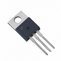
FDP8441 Fairchild Semiconductor, FDP8441 Datasheet

FDP8441
Specifications of FDP8441
Available stocks
Related parts for FDP8441
FDP8441 Summary of contents
Page 1
... GS Low Miller Charge Low Q Body Diode rr UIS Capability (Single Pulse and Repetitive Pulse) Qualified to AEC Q101 RoHS Compliant ©2006 Fairchild Semiconductor Corporation FDP8441 Rev.A ® MOSFET Applications Automotive Engine Control = 80A D Powertrain Management Solenoid and Motor Drivers Electronic Steering Integrated Starter / Alternator ...
Page 2
... R Gate Resistance G Q Total Gate Charge at 10V g(TOT) Q Threshold Gate Charge g(TH) Q Gate to Source Gate Charge gs Q Gate Charge Threshold to Plateau gs2 Q Gate to Drain “Miller” Charge gd FDP8441 Rev 25°C unless otherwise noted C Parameter o < 160 10V 10V, with C/W) GS θJA ...
Page 3
... This product has been designed to meet the extreme test conditions and environment demanded by the automotive industry. For a copy of the requirements, see AEC Q101 at: http://www.aecouncil.com/ All Fairchild Semiconductor products are manufactured, assembled and tested under ISO9000 and QS9000 quality systems FDP8441 Rev 25°C unless otherwise noted ...
Page 4
... SINGLE PULSE 1E Figure 3. 10000 V = 10V TRANSCONDUCTANCE GS MAY LIMIT CURRENT IN THIS REGION 1000 100 SINGLE PULSE FDP8441 Rev.A 300 250 200 150 100 125 150 175 ( Figure RECTANGULAR PULSE DURATION(s) Normalized Maximum Transient Thermal Impedance - RECTANGULAR PULSE DURATION(s) Figure 4 ...
Page 5
... DUTY CYCLE = 0.5% MAX 175 GATE TO SOURCE VOLTAGE GS Figure 9. Drain to Source On-Resistance Variation vs Gate to Source Voltage FDP8441 Rev.A 500 10us If R ≠ 100 AV 100us 10 STARTING T 1ms 10ms DC 1 0.01 100 NOTE: Refer to Fairchild Application Notes AN7514 and AN7515 Figure 6. Unclamped Inductive Switching 160 120 80 ...
Page 6
... T , JUNCTION TEMPERATURE J Figure 11. Normalized Gate Threshold Voltage vs Junction Temperature 40000 10000 1000 f = 1MHz 100 0 DRAIN TO SOURCE VOLTAGE DS Figure 13. Capacitance vs Drain to Source Voltage FDP8441 Rev.A 1. 250 µ 1.10 1.05 1.00 0.95 0.90 -80 80 120 160 200 Figure 12. Normalized Drain to Source ...
Page 7
... PRODUCT STATUS DEFINITIONS Definition of Terms Datasheet Identification Advance Information Preliminary No Identification Needed Obsolete FDP8441 Rev.A OCX™ SILENT SWITCHER OCXPro™ SMART START™ ® OPTOLOGIC SPM™ OPTOPLANAR™ ...


