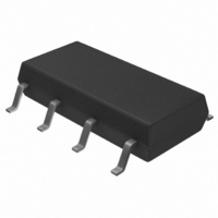
KA555IDTF Fairchild Semiconductor, KA555IDTF Datasheet - Page 8

KA555IDTF
Manufacturer Part Number
KA555IDTF
Description
IC TIMER CONTROLLER SGL 8-SOP
Manufacturer
Fairchild Semiconductor
Type
555 Type, Timer/Oscillator (Single)r
Datasheet
1.KA555IDTF.pdf
(14 pages)
Specifications of KA555IDTF
Voltage - Supply
4.5 V ~ 16 V
Current - Supply
7.5mA
Operating Temperature
-40°C ~ 85°C
Package / Case
8-SOIC (3.9mm Width)
Frequency
100kHz
Lead Free Status / RoHS Status
Lead free / RoHS Compliant
Count
-
KA555
KA555
4. Pulse Width Modulation
4. Pulse Width Modulation
The timer output waveform may be changed by modulating the control voltage applied to the timer's pin 5 and changing the
reference of the timer's internal comparators. Figure 9 illustrates the pulse width modulation circuit.
When the continuous trigger pulse train is applied in the monostable mode, the timer output width is modulated according to
the signal applied to the control terminal. Sine wave as well as other waveforms may be applied as a signal to the control
terminal. Figure 10 shows the example of pulse width modulation waveform.
5. Pulse Position Modulation
5. Pulse Position Modulation
If the modulating signal is applied to the control terminal while the timer is connected for the astable operation as in Figure 11,
the timer becomes a pulse position modulator.
In the pulse position modulator, the reference of the timer's internal comparators is modulated which in turn modulates the
timer output according to the modulation signal applied to the control terminal.
Figure 12 illustrates a sine wave for modulation signal and the resulting output pulse position modulation : however, any wave
shape could be used.
8 8 8 8
KA555
KA555
4. Pulse Width Modulation
4. Pulse Width Modulation
5. Pulse Position Modulation
5. Pulse Position Modulation
Figure 9. Circuit for Pulse Width Modulation
Figure 9. Circuit for Pulse Width Modulation
Figure 9. Circuit for Pulse Width Modulation
Figure 9. Circuit for Pulse Width Modulation
Trigger
Trigger
Trigger
Trigger
Output
Output
Output
Output
2
3
TRIG
OUT
RESET
4
GND
1
Vcc
THRES
DISCH
8
CONT
Figure 8. Waveforms of Frequency Divider Operation
Figure 8. Waveforms of Frequency Divider Operation
Figure 8. Waveforms of Frequency Divider Operation
Figure 8. Waveforms of Frequency Divider Operation
7
6
5
Input
Input
Input
Input
C C C C
R R R R
A A A A
+Vcc
+Vcc
+Vcc
+Vcc
Figure 10. Waveforms of Pulse Width Modulation
Figure 10. Waveforms of Pulse Width Modulation
Figure 10. Waveforms of Pulse Width Modulation
Figure 10. Waveforms of Pulse Width Modulation


