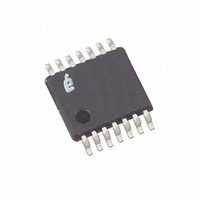
X9119TV14 Intersil, X9119TV14 Datasheet - Page 11

X9119TV14
Manufacturer Part Number
X9119TV14
Description
IC DCP 100K 1024TP 14TSSOP
Manufacturer
Intersil
Series
XDCP™r
Datasheet
1.X9119TV14.pdf
(17 pages)
Specifications of X9119TV14
Taps
1024
Resistance (ohms)
100K
Number Of Circuits
1
Temperature Coefficient
300 ppm/°C Typical
Memory Type
Non-Volatile
Interface
I²C, 2-Wire Serial
Voltage - Supply
4.5 V ~ 5.5 V
Operating Temperature
0°C ~ 70°C
Mounting Type
Surface Mount
Package / Case
14-TSSOP
Resistance In Ohms
100K
Lead Free Status / RoHS Status
Contains lead / RoHS non-compliant
Available stocks
Company
Part Number
Manufacturer
Quantity
Price
Company:
Part Number:
X9119TV14IZ-2.7
Manufacturer:
Intersil
Quantity:
254
Company:
Part Number:
X9119TV14IZ-2.7T1
Manufacturer:
DIODES
Quantity:
1 000
Company:
Part Number:
X9119TV14Z
Manufacturer:
Intersil
Quantity:
17
AC Test Conditions
Endurance and Data Retention
Capacitance
Power-Up Timing
NOTES:
Operating Specifications (Over the recommended operating conditions unless otherwise specified.)
I
Input Rise and Fall Times
Input and Output Timing Level
Minimum Endurance
Data Retention
V
Power-up to Initiation of read operation
Power-up to Initiation of write operation
Input/Output capacitance (SI)
Input capacitance (SCL, WP, A1 and A0)
nput Pulse Levels
V
(active)
V
(nonvolatile write)
V
Input leakage current
Output leakage
current
Input HIGH voltage
Input LOW voltage
Output LOW voltage
Output HIGH voltage
6. Limits should be considered typical and are not production tested.
7. t
8. Parameters with MIN and/or MAX limits are 100% tested at +25°C, unless otherwise specified. Temperature limits established by characterization
CC
CC
CC
CC
parameters are not 100% tested.
and are not production tested.
PUR
Power-up Rate
supply current
supply current
current (standby)
PARAMETER
and t
PUW
PARAMETER
are the delays required from the time the (last) power supply (Vcc-) is stable until the specific instruction can be issued. These
PARAMETER
TEST
11
SYMBOL
I
I
V
V
CC1
CC2
I
I
V
V
I
SB
LO
OH
LI
OL
IH
IL
V
10ns
V
CC
CC
x 0.1 to V
x 0.5
f
SDA = Open; (for 2-wire, Active, Read and
Volatile Write States only)
f
SDA = Open; (for 2-wire, Active,
Non-volatile Write State only)
V
SDA = V
(for 2-wire, Standby State only)
V
V
I
SCL
SCL
OL
CC
IN
OUT
= 3mA
= V
= +5.5V; V
= 400kHz; V
= 400kHz; V
= V
SS
CC
CC
SS
to V
;
100,000
t
t
t
x 0.9
r
PUR
PUW
to V
V
MIN
100
CC
CC
IN
TEST CONDITIONS
SYMBOL
CC
(Note 7)
CC
CC
(Note 7)
= V
(Note 6)
= +5.5V;
= +5.5V;
SS
X9119
C
C
or V
IN/OUT
IN
SYMBOL
(Note 6)
CC
;
(Note 6)
MIN
0.2
MAX
Data changes per bit per register
8
6
V
CC
MIN.
-1
x 0.7
UNITS
years
UNITS
MAX
50
50
pF
pF
1
TYP.
TEST CONDITIONS
V
V
CC
MAX.
CC
0.4
10
10
3
5
3
V
x 0.3
V
+ 1
OUT
IN
UNITS
V/ms
= 0V
ms
ms
= 0V
July 9, 2008
UNITS
mA
mA
FN8162.4
µA
µA
µA
V
V
V


