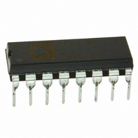
DAC8143FP Analog Devices Inc, DAC8143FP Datasheet - Page 2

DAC8143FP
Manufacturer Part Number
DAC8143FP
Description
IC DAC 12BIT DAISY-CHAIN 16-DIP
Manufacturer
Analog Devices Inc
Datasheet
1.DAC8143FSZ.pdf
(12 pages)
Specifications of DAC8143FP
Rohs Status
RoHS non-compliant
Settling Time
380ns
Number Of Bits
12
Data Interface
Serial
Number Of Converters
1
Voltage Supply Source
Single Supply
Power Dissipation (max)
500µW
Operating Temperature
-40°C ~ 85°C
Mounting Type
Through Hole
Package / Case
16-DIP (0.300", 7.62mm)
Number Of Channels
1
Resolution
12b
Interface Type
Serial (3-Wire)
Single Supply Voltage (typ)
5V
Dual Supply Voltage (typ)
Not RequiredV
Architecture
R-2R
Power Supply Requirement
Single
Output Type
Current
Integral Nonlinearity Error
±1LSB
Single Supply Voltage (min)
4.75V
Single Supply Voltage (max)
5.25V
Dual Supply Voltage (min)
Not RequiredV
Dual Supply Voltage (max)
Not RequiredV
Operating Temp Range
-40C to 85C
Operating Temperature Classification
Industrial
Mounting
Through Hole
Pin Count
16
Package Type
PDIP
Lead Free Status / Rohs Status
Not Compliant
Available stocks
Company
Part Number
Manufacturer
Quantity
Price
Part Number:
DAC8143FPZ
Manufacturer:
ADI/亚德诺
Quantity:
20 000
DAC8143–SPECIFICATIONS
ELECTRICAL CHARACTERISTICS
Parameter
STATIC ACCURACY
AC PERFORMANCE
DIGITAL INPUTS/OUTPUT
ANALOG OUTPUTS
TIMING CHARACTERISTICS
Digital-to-Analog Glitch Energy
Digital Output Low
Resolution
Nonlinearity
Differential Nonlinearity
Gain Error
Gain Tempco ( Gain/ Temp)
Power Supply Rejection Ratio
Output Leakage Current
Zero Scale Error
Input Resistance
Output Current Settling Time
AC Feedthrough Error
Total Harmonic Distortion
Output Noise Voltage Density
Digital Input HIGH
Digital Input LOW
Input Leakage Current
Input Capacitance
Digital Output High
Output Capacitance
Output Capacitance
Serial Input to Strobe Setup Times
Serial Input to Strobe Hold Times
(V
( Gain/ V
(t
(t
STB
REF
STB
= 80 ns)
to I
= 80 ns)
2
OUT1
DD
)
)
5, 6
7
3, 9
3
3
12
1
4
3
3, 8
3, 11
3, 10
3
3
Symbol
N
INL
DNL
G
TC
PSRR
I
I
R
t
FT
Q
THD
e
V
V
I
C
V
V
C
C
C
C
t
t
t
t
t
t
t
t
S
DS1
DS2
DS3
DS4
DH1
DH2
DH3
DH4
LKG
ZSE
IN
n
IN
IH
IL
OH
OL
IN
OUT1
OUT2
OUT1
OUT2
FSE
GFS
(@ V
Range specified under Absolute Maximum Ratings, unless otherwise noted.)
Conditions
T
T
T
T
V
V
V
V
DAC Register Loaded with All 1s
10 Hz to 100 kHz Between R
V
V
I
I
Digital Inputs = All 1s
Digital Inputs = All 0s
Digital Inputs = All 0s
Digital Inputs = All 1s
STB
STB
STB
STB
STB
STB
STB
STB
OH
OL
V
REF
REF
A
A
A
A
REF
REF
IN
IN
DD
= +25 C
= Full Temperature Range
= +25 C
= Full Temperature Range
= 1.6 mA
DD
= 0 V to +5 V
= 0 V
= –200 A
3
4
1
2
3
4
1
2
= 20 V p-p @ f = 10 kHz, T
= 0 V, I
Pin
= 6 V rms @ 1 kHz
Used as the Strobe T
Used as the Strobe
Used as the Strobe T
Used as the Strobe T
Used as the Strobe
Used as the Strobe
= 5%
Used as the Strobe
Used as the Strobe
= +5 V; V
OUT
–2–
REF
Load = 100 , C
= +10 V; V
T
T
T
A
A
A
A
A
A
= Full Temperature Range 20
= Full Temperature Range 50
= Full Temperature Range 60
= +25 C
= +25 C
= +25 C
FB
OUT1
and I
A
EXT
= +25 C
= V
= 13 pF
OUT
OUT2
= V
AGND
= V
DGND
Min
12
7
2.4
4
10
20
40
50
80
80
50
20
= 0 V; T
Typ
11
0.380
0.0006 0.002 %/%
0.002
0.01
A
= Full Temperature
15
1
2.0
20
–92
13
0.8
8
0.4
90
90
60
60
Max
1
1
2
5
5
25
0.03
0.15
1
REV. C
Units
Bits
LSB
LSB
LSB
ppm/ C
nA
nA
LSB
LSB
k
mV p-p
nVs
dB
nV/ Hz
V
V
pF
V
V
pF
pF
pF
pF
ns
ns
ns
ns
ns
ns
ns
ns
ns
ns
ns
s
A


