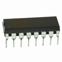
DAC8143FP Analog Devices Inc, DAC8143FP Datasheet - Page 5

DAC8143FP
Manufacturer Part Number
DAC8143FP
Description
IC DAC 12BIT DAISY-CHAIN 16-DIP
Manufacturer
Analog Devices Inc
Datasheet
1.DAC8143FSZ.pdf
(12 pages)
Specifications of DAC8143FP
Rohs Status
RoHS non-compliant
Settling Time
380ns
Number Of Bits
12
Data Interface
Serial
Number Of Converters
1
Voltage Supply Source
Single Supply
Power Dissipation (max)
500µW
Operating Temperature
-40°C ~ 85°C
Mounting Type
Through Hole
Package / Case
16-DIP (0.300", 7.62mm)
Number Of Channels
1
Resolution
12b
Interface Type
Serial (3-Wire)
Single Supply Voltage (typ)
5V
Dual Supply Voltage (typ)
Not RequiredV
Architecture
R-2R
Power Supply Requirement
Single
Output Type
Current
Integral Nonlinearity Error
±1LSB
Single Supply Voltage (min)
4.75V
Single Supply Voltage (max)
5.25V
Dual Supply Voltage (min)
Not RequiredV
Dual Supply Voltage (max)
Not RequiredV
Operating Temp Range
-40C to 85C
Operating Temperature Classification
Industrial
Mounting
Through Hole
Pin Count
16
Package Type
PDIP
Lead Free Status / Rohs Status
Not Compliant
Available stocks
Company
Part Number
Manufacturer
Quantity
Price
Part Number:
DAC8143FPZ
Manufacturer:
ADI/亚德诺
Quantity:
20 000
REV. C
Figure 7. Logic Threshold Voltage
vs. Supply Voltage
Figure 4. Supply Current vs. Logic
Input Voltage
–0.8
2.4
DATA BITS "OFF")
DATA BITS "ON"
4
3
2
1
0
3
2
1
0
1
(ALL OTHER
0
3
Figure 2. Multiplying Mode Frequency
Response vs. Digital Code
1
ALL BITS ON
5
(MSB) B11
(LSB) B0
7
V
V
2
DD
B10
IN
B9
B8
B7
B6
B5
B4
B3
B2
B1
– Volts
– Volts
9
100
3
11
1k
13
4
FREQUENCY – Hz
15
10k
17
5
100k
Code
Figure 5. Linearity Error vs. Digital
1M
Figure 8. DNL Error vs. Reference
Voltage
–0.25
–0.1
–0.2
–0.3
–0.4
–0.5
0.25
–0.5
0.5
0.4
0.3
0.2
0.1
0.0
0.5
0
0
2
10M
Typical Performance Characteristics–
0
12
24
36
48
60
72
84
96
108
512
DIGITAL INPUT CODE – Decimal
1024
4
1536
V
–5–
REF
2048
6
– Volts
2560
3072
8
Figure 3. Multiplying Mode Total Harmonic
Distortion vs. Frequency
3584
–70
–75
–80
–85
–90
–95
4095
10
10
V
OUTPUT OP AMP: OP-42
IN
= 5V rms
100
FREQUENCY – Hz
Figure 6. Linearity Error vs. Refer-
Figure 9. Digital Output Voltage vs.
Output Current
ence Voltage
–0.25
0.25
–0.5
0.5
–10
–20
–30
–40
40
30
20
10
0
0
1k
2
0
T
A
= +25 C
SRO – VOLTAGE OUT – Volts
1
10k
4
V
REF
2
LOGIC 0
LOGIC 1
100k
DAC8143
6
– Volts
0.032
0.018
0.010
0.0056
0.0032
0.0018
3
8
4
10
5


