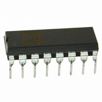
DAC8143FP Analog Devices Inc, DAC8143FP Datasheet - Page 3

DAC8143FP
Manufacturer Part Number
DAC8143FP
Description
IC DAC 12BIT DAISY-CHAIN 16-DIP
Manufacturer
Analog Devices Inc
Datasheet
1.DAC8143FSZ.pdf
(12 pages)
Specifications of DAC8143FP
Rohs Status
RoHS non-compliant
Settling Time
380ns
Number Of Bits
12
Data Interface
Serial
Number Of Converters
1
Voltage Supply Source
Single Supply
Power Dissipation (max)
500µW
Operating Temperature
-40°C ~ 85°C
Mounting Type
Through Hole
Package / Case
16-DIP (0.300", 7.62mm)
Number Of Channels
1
Resolution
12b
Interface Type
Serial (3-Wire)
Single Supply Voltage (typ)
5V
Dual Supply Voltage (typ)
Not RequiredV
Architecture
R-2R
Power Supply Requirement
Single
Output Type
Current
Integral Nonlinearity Error
±1LSB
Single Supply Voltage (min)
4.75V
Single Supply Voltage (max)
5.25V
Dual Supply Voltage (min)
Not RequiredV
Dual Supply Voltage (max)
Not RequiredV
Operating Temp Range
-40C to 85C
Operating Temperature Classification
Industrial
Mounting
Through Hole
Pin Count
16
Package Type
PDIP
Lead Free Status / Rohs Status
Not Compliant
Available stocks
Company
Part Number
Manufacturer
Quantity
Price
Part Number:
DAC8143FPZ
Manufacturer:
ADI/亚德诺
Quantity:
20 000
REV. C
ELECTRICAL CHARACTERISTICS
Temperature Range specified under Absolute Maximum Ratings, unless otherwise noted.)
Parameter
STB to SRO Propagation Delay
SRI Data Pulsewidth
STB
STB
STB
STB
Load Pulsewidth
LSB Strobe into Input Register
CLR Pulsewidth
POWER SUPPLY
NOTES
11
12
13
14
15
16
17
18
19
10
11
12
13
14
Specifications subject to change without notice.
All grades are monotonic to 12 bits over temperature.
Using internal feedback resistor.
Guaranteed by design and not tested.
Applies to I
V
Calculated from worst case R
Absolute temperature coefficient is less than +300 ppm/ C.
I
All digital inputs = 0 V.
V
Calculations from e
Digital inputs are CMOS gates; I
Measured from active strobe edge (STB) to new data output at SRO; C
Minimum low time pulsewidth for STB
time constant of the final RC decay.
K = Boltzmann constant, J/KR = resistance
T = resistor temperature, K B = bandwidth, Hz
Supply Voltage
OUT
to Load DAC Register Time
Supply Current
Power Dissipation
REF
REF
1
2
3
4
, Load = 100 . C
Pulsewidth (STB1 = 80 ns)
Pulsewidth (STB2 = 100 ns)
Pulsewidth (STB3 = 80 ns)
Pulsewidth (STB4 = 80 ns)
= +10 V, all digital inputs = 0 V.
= 0 V, all digital inputs = 0 V to V
OUT1
; all digital inputs = V
n
= 4K TRB where:
EXT
= 13 pF, digital input = 0 V to V
REF
: I
IN
13
ZSE
typically 1 nA at +25 C.
14
14
14
14
IL
(in LSBs) = (R
, V
1
DD
, STB
REF
or V
= +10 V; specification also applies for I
2
DD
, and STB
to 0 V.
REF
Symbol
t
t
t
t
t
t
t
t
t
V
I
P
PD
SRI
STB1
STB2
STB3
STB4
LD1
ASB
CLR
DD
DD
D
4
, t
, and minimum high time pulsewidth for STB
I
LKG
(@ V
DD
LD2
or V
DD
4096) /V
DD
= +5 V; V
to 0 V. Extrapolated to 1/2 LSB: t
L
Conditions
T
T
T
T
All Digital Inputs = V
All Digital Inputs = 0 V or V
Digital Inputs = 0 V or V
5 V
Digital Inputs = V
5 V
= 50 pF.
REF
A
A
A
A
= +25 C
= Full Temperature Range
= +25 C
= Full Temperature Range
.
REF
–3–
0.1 mA
2 mA
= +10 V; V
OUT2
when all digital inputs = V
IH
OUT1
or V
IH
= V
or V
DD
IL
3
0UT2
S
.
IL
DD
= propagation delay (t
= V
AGND
IH
= V
.
Min
100
80
80
80
80
140
180
0
80
4.75
DGND
= 0 V; T
DAC8143
PD
) +9 , where equals measured
Typ
5
A
= Full
Max
220
300
5.25
2
0.1
0.5
10
DAC8143
Units
ns
ns
ns
ns
ns
ns
ns
ns
ns
ns
ns
V
mA
mA
mW
mW


