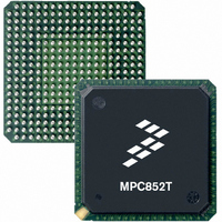
MPC852TCVR100A Freescale Semiconductor, MPC852TCVR100A Datasheet - Page 11

MPC852TCVR100A
Manufacturer Part Number
MPC852TCVR100A
Description
IC MPU POWERQUICC 100MHZ 256PBGA
Manufacturer
Freescale Semiconductor
Datasheet
1.MPC852TVR50A.pdf
(80 pages)
Specifications of MPC852TCVR100A
Processor Type
MPC8xx PowerQUICC 32-Bit
Speed
100MHz
Voltage
1.8V
Mounting Type
Surface Mount
Package / Case
256-PBGA
Processor Series
MPC8xx
Core
MPC8xx
Data Bus Width
32 bit
Development Tools By Supplier
MPC852TADS-KIT
Maximum Clock Frequency
100 MHz
Operating Supply Voltage
0 V to 3.3 V
Maximum Operating Temperature
+ 105 C
Mounting Style
SMD/SMT
Data Ram Size
8 KB
Minimum Operating Temperature
- 40 C
Program Memory Size
4 KB
Program Memory Type
EPROM/Flash
Lead Free Status / RoHS Status
Lead free / RoHS Compliant
Features
-
Lead Free Status / Rohs Status
Details
Available stocks
Company
Part Number
Manufacturer
Quantity
Price
Company:
Part Number:
MPC852TCVR100A
Manufacturer:
FREESCAL
Quantity:
300
Company:
Part Number:
MPC852TCVR100A
Manufacturer:
Freescale Semiconductor
Quantity:
10 000
If the board temperature is known and the heat loss from the package case to the air can be ignored,
acceptable predictions of junction temperature can be made. For this method to work, the board and board
mounting must be similar to the test board used to determine the junction-to-board thermal resistance,
namely a 2s2p (board with a power and a ground plane) and vias attaching the thermal balls to the ground
plane.
7.4
When the board temperature is not known, a thermal simulation of the application is needed. The simple
two-resistor model can be used with the thermal simulation of the application [2], or a more accurate and
complex model of the package can be used in the thermal simulation.
7.5
To determine the junction temperature of the device in the application after prototypes are available, the
thermal characterization parameter (Ψ
measurement of the temperature at the top center of the package case using the following equation:
where:
The thermal characterization parameter is measured per JESD51-2 specification published by JEDEC
using a 40-gauge type T thermocouple epoxied to the top center of the package case. The thermocouple
should be positioned so that the thermocouple junction rests on the package. A small amount of epoxy is
placed over the thermocouple junction and over about 1 mm of wire extending from the junction. The
thermocouple wire is placed flat against the package case to avoid measurement errors that cooling effects
of the thermocouple wire cause.
8
Freescale Semiconductor
1. C.E. Triplett and B. Joiner, “An Experimental Characterization of a 272 PBGA Within an
2. B. Joiner and V. Adams, “Measurement and Simulation of Junction to Board Thermal Resistance
Ψ
T
P
References
Semiconductor Equipment and Materials International (415) 964-5111
805 East Middlefield Rd
Mountain View, CA 94043
MIL-SPEC and EIA/JESD (JEDEC) specifications
(Available from Global Engineering documents)
JEDEC Specifications
Automotive Engine Controller Module,” Proceedings of SemiTherm, San Diego, 1998, pp. 47–54.
and Its Application in Thermal Modeling,” Proceedings of SemiTherm, San Diego, 1999,
pp. 212–220.
D
T
JT
Estimation Using Simulation
Experimental Determination
= thermocouple temperature on top of package
= power dissipation in package
= thermal characterization parameter
T
J
= T
T
+ (Ψ
MPC852T PowerQUICC™ Hardware Specifications, Rev. 4
JT
× P
D
)
JT
) can be used to determine the junction temperature with a
303-397-7956
800-854-7179 or
http://www.jedec.org
References
11


