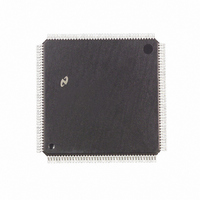
DP83905AVQB National Semiconductor, DP83905AVQB Datasheet - Page 47

DP83905AVQB
Manufacturer Part Number
DP83905AVQB
Description
IC CONTROLR AT/LAN TP IN 160PQFP
Manufacturer
National Semiconductor
Series
AT/LANTIC™r
Datasheet
1.DP83905AVQB.pdf
(80 pages)
Specifications of DP83905AVQB
Controller Type
AT, LAN Twisted-Pair Interface Controller
Voltage - Supply
4.75 V ~ 5.25 V
Current - Supply
100mA
Operating Temperature
0°C ~ 70°C
Mounting Type
Surface Mount
Package / Case
160-BFQFP
Lead Free Status / RoHS Status
Contains lead / RoHS non-compliant
Interface
-
Other names
*DP83905AVQB
Available stocks
Company
Part Number
Manufacturer
Quantity
Price
Company:
Part Number:
DP83905AVQB
Manufacturer:
Texas Instruments
Quantity:
10 000
Part Number:
DP83905AVQB
Manufacturer:
NS/国半
Quantity:
20 000
6 0 Operation of AT LANTIC Controller
10 Take the AT LANTIC Controller out of loopback This is
11 lf the ‘‘Resend’’ variable is set to a 1 reset the ‘‘Re-
Note 1 If Remote DMA is not being used the AT LANTIC Controller does
Note 2 When the AT LANTIC Controller is in STOP mode the Missed
4 Clear the AT LANTIC Controller’s Remote Byte Count
5 Read the stored value of the TXP bit from step 1
6 Place the AT LANTIC Controller in either mode 1 or
7 Issue the START command to the AT LANTIC Control-
8 Remove one or more packets from the receive buffer
9 Reset the overwrite warning (OVW overflow) bit in the
done by Writing the Transmit Configuration Register
with the value it contains during normal operation (Bits
D2 and D1 should both be programmed to 0 )
send’’ variable and reissue the transmit command This
is done by writing a value of 26H to the Command Reg-
ister If the ‘‘Resend’’ variable is 0 nothing needs to be
done
registers (RBCR0 and RBCR1)
above
If this value is a 0 set the ‘‘Resend’’ variable to a 0 and
jump to step 6
If this value is a 1 read the AT LANTIC Controller’s
Interrupt Status Register If either the Packet Transmit-
ted bit (PTX) or Transmit Error bit (TXE) is set to a 1 set
the ‘‘Resend’’ variable to a 0 and jump to step 6 If
neither of these bits is set place a 1 in the ‘‘Resend’’
variable and jump to step 6
This step determines if there was a transmission in
progress when the stop command was issued in step 2
If there was a transmission in progress the AT LANTIC
Controller’s ISR is read to determine whether or not the
packet was recognized by the AT LANTIC Controller If
neither the PTX nor TXE bit was set then the packet
will essentially be lost and re-transmitted only after a
time-out takes place in the upper level software By de-
termining that the packet was lost at the driver level a
transmit command can be reissued to the AT LANTIC
Controller once the overflow routine is completed (as in
step 11) Also it is possible for the AT LANTIC Control-
ler to defer indefinitely when it is stopped on a busy
network Step 5 also alleviates this problem Step 5 is
essential and should not be omitted from the overflow
routine in order for the AT LANTIC Controller to oper-
ate correctly
mode 2 Ioopback This can be accomplished by setting
bits D2 and D1 of the Transmit Configuration Register
to 0 1 or 1 0 respectively
ler This can be accomplished by Writing 22H to the
Command Register This is necessary to activate the
AT LANTIC Controller’s Remote DMA channel
ring
Interrupt Status Register
not need to be started before packets can be removed from the
receive buffer ring Hence step 8 could be done before step 7
eliminating or reducing the time spent polling in step 5
Packet Tally counter is disabled
47
(Continued)
FIGURE 32 Overflow Routine
TL F 11498 – 29


