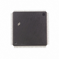
DP83905AVQB National Semiconductor, DP83905AVQB Datasheet - Page 49

DP83905AVQB
Manufacturer Part Number
DP83905AVQB
Description
IC CONTROLR AT/LAN TP IN 160PQFP
Manufacturer
National Semiconductor
Series
AT/LANTIC™r
Datasheet
1.DP83905AVQB.pdf
(80 pages)
Specifications of DP83905AVQB
Controller Type
AT, LAN Twisted-Pair Interface Controller
Voltage - Supply
4.75 V ~ 5.25 V
Current - Supply
100mA
Operating Temperature
0°C ~ 70°C
Mounting Type
Surface Mount
Package / Case
160-BFQFP
Lead Free Status / RoHS Status
Contains lead / RoHS non-compliant
Interface
-
Other names
*DP83905AVQB
Available stocks
Company
Part Number
Manufacturer
Quantity
Price
Company:
Part Number:
DP83905AVQB
Manufacturer:
Texas Instruments
Quantity:
10 000
Part Number:
DP83905AVQB
Manufacturer:
NS/国半
Quantity:
20 000
6 0 Operation of AT LANTIC Controller
Error Recovery
If the packet is rejected as shown the DMA is restored by
the AT LANTIC Controller by reprogramming the DMA
starting address pointed to by the Current Page Register
Storage Format for Received Packets
The following diagrams describe the format for how re-
ceived packets are placed into memory by the local DMA
channel These modes are selected in the Data Configura-
tion Register
BOS
Series 32xxx or 808xx processors
BOS
680x0 type processors (Note The Receiver Count ordering remains the
same for BOS
6 4 PACKET TRANSMISSION
The Local DMA is also used during transmission of a pack-
et Three registers control the DMA transfer during trans-
mission a Transmit Page Start Address Register (TPSR)
and the Transmit Byte Count Registers (TBCR0 1) When
the AT LANTIC Controller receives a command to transmit
the packet pointed to by these registers buffer memory
data will be moved into the FIFO as required during trans-
mission The AT LANTIC Controller will generate and ap-
pend the preamble synch and CRC fields
Transmit Packet Assembly
The AT LANTIC Controller requires a contiguous assem-
bled packet with the format shown The transmit byte count
includes the Destination Address Source Address Length
Field and Data It does not include preamble and CRC
AD15
AD15
e
e
Receive Byte Count 1
Receive Byte Count 0
Next Packet Pointer
Next Packet Pointer
TBCR0 1
0 WTS
1 WTS
Transmit
BOS
format is used with general 8-bit processors
Count
Byte
e
e
Byte 2
Byte 1
General Transmit Packet Format
e
e
0 WTS
0 or 1 )
1 in Data Configuration Register This format is used with
1 in Data Configuration Register This format is used with
Pad (If data
Receive Byte Count 0
Receive Byte Count 1
Destination Address
Next Packet Pointer
e
Source Address
Receive Status
AD8
AD8
0 in Data Configuration Register This
Type Length
Byte 0
Byte 1
Data
k
46 Bytes)
AD7
AD7
Receive Byte Count 0
Receive Byte Count 1
Receive Status
Receive Status
Byte 1
Byte 2
t
6 Bytes
6 Bytes
2 Bytes
46 Bytes
AD0
AD0
49
(Continued)
When transmitting data smaller than 46 bytes the packet
must be padded to a minimum size of 64 bytes The pro-
grammer is responsible for adding and stripping pad bytes
The packets are placed in the buffer RAM by the system In
I O Mode the system programs the NIC Core’s Remote
DMA to mode the data from the data port to the RAM hand-
shaking with system transfers loading the I O data port In
Shared Memory Mode the packets are written directly to the
RAM by system using standard memory transfer instruc-
tions (MOV)
For I O mode the data transfer must be 16 bits (1 word)
when in 16-bit mode and 8 bits when the AT LANTIC Con-
troller is set in 8-bit mode The data width is selected by
setting the WTS bit in the Data Configuration Register and
setting the DWlD pin for the proper mode
In Shared Memory mode data transfer can be accomplished
by using either 8- or 16-bit data transfer instructions be-
cause this mode responds to 8 16-bit data signalling on the
ISA bus In this mode Shared Memory Control Register 2-bit
6 sets the bus interface data width and the NIC Core’s data
width is set by the WTS bit in the Data Configuration Regis-
ter
Transmission
Prior to transmission the TPSR (Transmit Page Start Regis-
ter) and TBCR0 TBCR1 (Transmit Byte Count Registers)
must be initialized To initiate transmission of the packet the
TXP bit in the Command Register is set The Transmit
Status Register (TSR) is cleared and the AT LANTIC Con-
troller begins to prefetch transmit data from memory (unless
the AT LANTIC Controller is currently receiving) If the inter-
frame gap has timed out the AT LANTIC Controller will be-
gin transmission
Conditions Required to Begin Transmission
In order to transmit a packet the following three conditions
must be met
1 The Interframe Gap Timer has timed out the first 6 4 s
2 At least one byte has entered the FIFO (This indicates
3 If a collision had been detected then before transmission
In typical systems the AT LANTIC Controller prefetches the
first burst of bytes before the 6 4 s timer expires The time
during which AT LANTIC Controller transmits preamble can
also be used to load the FIFO
Note If carrier sense is asserted before a byte has been loaded into the
Collision Recovery
During transmission the Buffer Management logic monitors
the transmit circuitry to determine if a collision has occurred
If a collision is detected the Buffer Management logic will
reset the FIFO and restore the Transmit DMA pointers for
retransmission of the packet The COL bit will be set in the
TSR and the NCR (Number of Collisions Register) will be
incremented If 15 retransmissions each result in a collision
the transmission will be aborted and the ABT bit in the TSR
will be set
Note NCR reads as zeroes if excessive collisions are encountered
of the Interframe Gap
that the burst transfer has been started)
the packet time must have timed out
FIFO the AT LANTIC Controller will become a receiver


