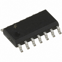
USB1T11AMX Fairchild Semiconductor, USB1T11AMX Datasheet - Page 2

USB1T11AMX
Manufacturer Part Number
USB1T11AMX
Description
IC TXRX SERIAL BUS UNIV 14SOIC
Manufacturer
Fairchild Semiconductor
Type
Transceiverr
Datasheet
1.USB1T11AMTC.pdf
(10 pages)
Specifications of USB1T11AMX
Number Of Drivers/receivers
1/1
Protocol
USB 1.1
Voltage - Supply
3.3V
Mounting Type
Surface Mount
Package / Case
14-SOIC (3.9mm Width), 14-SOL
Number Of Receivers
1
Number Of Transmitters
1
Maximum Operating Temperature
+ 85 C
Mounting Style
SMD/SMT
Maximum Data Rate
12 Mbps
Maximum Supply Current
5 mA
Minimum Operating Temperature
- 40 C
Protocol Supported
USB 1.1
Number Of Transceivers
1
Esd Protection
YeskV
Power Supply Requirement
Single
Operating Supply Voltage (typ)
3.3V
Operating Temperature Classification
Industrial
Operating Supply Voltage (max)
3.6V
Operating Supply Voltage (min)
3V
Dual Supply Voltage (typ)
Not RequiredV
Dual Supply Voltage (max)
Not RequiredV
Dual Supply Voltage (min)
Not RequiredV
Pin Count
14
Mounting
Surface Mount
Operating Temperature (max)
85C
Operating Temperature (min)
-40C
Lead Free Status / RoHS Status
Lead free / RoHS Compliant
Other names
USB1T11AMX_NL
USB1T11AMX_NLTR
USB1T11AMX_NLTR
USB1T11AMX_NLTR
USB1T11AMX_NLTR
Available stocks
Company
Part Number
Manufacturer
Quantity
Price
Part Number:
USB1T11AMX
Manufacturer:
FAIRCHILD/仙童
Quantity:
20 000
Company:
Part Number:
USB1T11AMX/NOPB
Manufacturer:
TI
Quantity:
4 310
© 1999 Fairchild Semiconductor Corporation
USB1T11A • Rev. 1.0.4
Pin Configuration
Pin Descriptions
V
Pin Names
PO
SUSPND
D+, D-
Speed
,V
V
Mode
GND
RCV
/OE
V
P
MO
,V
CC
/F
M
SEO
AI/O
I/O
O
O
I
I
I
I
I
Receive Data. CMOS level output for USB differential input.
Output Enable. Active LOW, enables the transceiver to transmit data on the bus.
When not active, the transceiver is in receive mode.
Mode. When left unconnected, a weak pull-up transistor pulls it to V
GND, the V
Inputs to differential driver. (Outputs from SIE.)
Buffered version of D- and D+. Outputs are logic “0” and logic “1.” Used to detect
single ended zero (/SEO), error conditions, and interconnected speed. (Input to SIE).
Data+, Data-. Differential data bus conforming to the Universal Serial Bus standard.
Suspend. Enables a low-power state while the USB bus is inactive. While the
suspend pin is active, it drives the RCV pin to a logic “0” state. Both D+ and D- are 3-
STATE.
Edge Rate Control. Logic “1” operates at edge rates for “full speed.” Logic “0”
operates edge rates for “low speed.”
3.0 to 3.6 power supply.
Ground reference.
Figure 2. TSSOP and SOIC Pin Assignments
Mode
0
0
0
0
1
1
1
1
SUSPND
MO
MODE
V
GND
0
0
1
0
RCV
/OE
/F
P
V
V
M
P
SEO
1
2
3
4
5
6
7
pin takes the function of F
2
V
0
0
1
1
0
0
1
1
PO
14
13
12
10
11
9
8
Description
V
V
V
D+
D-
SPEED
NC
CC
MO
PO
/F
V
SEO
0
1
0
1
M
SEO
V
(force SEO).
MO
/F
0
1
0
1
0
1
0
1
SEO
Low Speed
Full Speed
RESULT
CC
/SEO
Error
Illegal Code
and, in this
RESULT
Logic “0”
Logic “1”
Logic “0”
Logic “1”
/SEO
/SEO
/SEO
www.fairchildsemi.com


