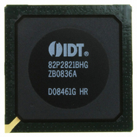
IDT82P2821BHG IDT, Integrated Device Technology Inc, IDT82P2821BHG Datasheet - Page 49

IDT82P2821BHG
Manufacturer Part Number
IDT82P2821BHG
Description
IC LINE INTERFACE UNIT 640-PBGA
Manufacturer
IDT, Integrated Device Technology Inc
Datasheet
1.IDT82P2821BHG.pdf
(151 pages)
Specifications of IDT82P2821BHG
Function
Line Interface Unit (LIU)
Interface
E1, J1, T1
Number Of Circuits
1
Voltage - Supply
1.8V, 3.3V
Operating Temperature
-40°C ~ 85°C
Mounting Type
Surface Mount
Package / Case
*
Includes
Defect and Alarm Detection, Driver Over-Current Detection and Protection, LLOS Detection, PRBSARB / IB Detection and Generation
Number Of Transceivers
1
Screening Level
Industrial
Mounting
Surface Mount
Operating Temperature (min)
-40C
Operating Temperature (max)
85C
Lead Free Status / RoHS Status
Lead free / RoHS Compliant
Current - Supply
-
Power (watts)
-
Lead Free Status / RoHS Status
Compliant, Lead free / RoHS Compliant
Other names
800-1703
82P2821BHG
82P2821BHG
Available stocks
Company
Part Number
Manufacturer
Quantity
Price
Company:
Part Number:
IDT82P2821BHG
Manufacturer:
IDT
Quantity:
170
Company:
Part Number:
IDT82P2821BHG
Manufacturer:
IDT, Integrated Device Technology Inc
Quantity:
10 000
3.5.5.2 Pattern Detection
system side may be extracted for pattern detection. The direction of data
extraction is determined by the PD_POS bit (b3, PD,...). One of PRBS or
ARB pattern is selected for detection and IB detection is always active.
data should be decoded by using AMI or B8ZS (for T1/J1) / HDB3 (for
E1). The decoding rule is selected by the R_CODE bit (b2, RCF1,...).
the data should be decoded by using AMI or B8ZS (for T1/J1) / HDB3
(for E1) in Transmit Dual Rail NRZ Format mode and Transmit Dual Rail
RZ Format mode. The decoding rule is selected by the T_CODE bit (b2,
TCF1,...).
Pseudo Random Bit Sequence (PRBS) /Arbitrary Pattern (ARB)
Detection
(b2, PD,...) before PRBS/ARB detection.
desired pattern is re-generated from the extracted data if the desired
pattern is (2^20 - 1) QRSS per O.150-4.5, (2^15 - 1) PRBS per O.152 or
(2^11 - 1) PRBS per O.150; or the desired pattern is programmed in the
ARB[23:0] bits (b7~0, ARBH~ARBM~ARBL,...) if the desired pattern is
ARB. The desired pattern is selected by the PAD_SEL[1:0] bits (b1~0,
PD,...).
programming and pattern comparison is shown in Figure-28.
Functional Description
IDT82P2821
Data received from the line side or data input from the transmit
If data is extracted from the receive path, before pattern detection the
If data is extracted from the transmit path, before pattern detection
The extracted data can be optionally inverted by the PAD_INV bit
The extracted data is used to compare with the desired pattern. The
In summary, do the followings step by step to detect PRBS/ARB:
• Select the detection direction by the PD_POS bit (b3, PD,...);
• Set the ARB[23:0] bits (b7~0, ARBH~ARBM~ARBL,...) if the ARB
• Select the desired PRBS/ARB pattern by the PAD_SEL[1:0] bits
The priority of decoding, data inversion, pattern re-generation, bit
pattern is desired - this step is omitted if the PRBS pattern is
desired;
(b1~0, PD,...).
21(+1) CHANNEL HIGH-DENSITY T1/E1/J1 LINE INTERFACE UNIT
49
ated PRBS pattern or the programmed ARB pattern for more than 64-bit
hopping window, the pattern is synchronized and the PA_S bit (b5,
STAT1,...) will be set.
detected in a 64-bit hopping window, the pattern is out of synchroniza-
tion and the PA_S bit (b5, STAT1,...) will be cleared.
ARB error. When a PRBS/ARB error is detected during the synchroniza-
tion, the ERR_IS bit (b1, INTS2,...) will be set and an interrupt will be
reported by INT if not masked by the ERR_IM bit (b1, INTM2,...). The
PRBS/ARB error may be counted by an internal Error Counter. Refer to
Section 3.5.6 Error Counter.
sition (from ‘0’ to ‘1’ or from ‘1’ to ‘0’) on the PA_S bit (b5, STAT1,...) will
set the PA_IS bit (b5, INTS1,...) to ‘1’, as selected by the PA_IES bit (b5,
INTES,...). When the PA_IS bit (b5, INTS1,...) is ‘1’, an interrupt will be
reported by INT if not masked by the PA_IM bit (b5, INTM1,...).
RMFn or TMFn pin. Refer to Section 3.5.7 Receive /Transmit Multiplex
Function (RMF / TMF) Indication.
from Rx path
or Tx path
During comparison, if the extracted data coincides with the re-gener-
In synchronization state, if more than 6 PRBS/ARB errors are
In synchronization state, each mismatched bit will generate a PRBS/
A transition from ‘0’ to ‘1’ on the PA_S bit (b5, STAT1,...) or any tran-
The PRBS/ARB synchronization status may be indicated by the
Figure-28 PRBS / ARB Detection
Decoding
Inversion
Data
Programming
Generation
PRBS Re-
ARB[23:0]
February 6, 2009
Comparison


