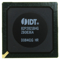
IDT82P2821BHG IDT, Integrated Device Technology Inc, IDT82P2821BHG Datasheet - Page 56

IDT82P2821BHG
Manufacturer Part Number
IDT82P2821BHG
Description
IC LINE INTERFACE UNIT 640-PBGA
Manufacturer
IDT, Integrated Device Technology Inc
Datasheet
1.IDT82P2821BHG.pdf
(151 pages)
Specifications of IDT82P2821BHG
Function
Line Interface Unit (LIU)
Interface
E1, J1, T1
Number Of Circuits
1
Voltage - Supply
1.8V, 3.3V
Operating Temperature
-40°C ~ 85°C
Mounting Type
Surface Mount
Package / Case
*
Includes
Defect and Alarm Detection, Driver Over-Current Detection and Protection, LLOS Detection, PRBSARB / IB Detection and Generation
Number Of Transceivers
1
Screening Level
Industrial
Mounting
Surface Mount
Operating Temperature (min)
-40C
Operating Temperature (max)
85C
Lead Free Status / RoHS Status
Lead free / RoHS Compliant
Current - Supply
-
Power (watts)
-
Lead Free Status / RoHS Status
Compliant, Lead free / RoHS Compliant
Other names
800-1703
82P2821BHG
82P2821BHG
Available stocks
Company
Part Number
Manufacturer
Quantity
Price
Company:
Part Number:
IDT82P2821BHG
Manufacturer:
IDT
Quantity:
170
Company:
Part Number:
IDT82P2821BHG
Manufacturer:
IDT, Integrated Device Technology Inc
Quantity:
10 000
3.5.8.3 Digital Loopback
Either manual Digital Loopback configuration or automatic Digital Loop-
back configuration will enable Digital Loopback.
assigned in the transmit path (i.e., the PD_POS bit (b3, PD,...) is ‘1’) and
the AUTOLP bit (b3, LOOP,...) is ‘1’. The corresponding channel will
enter Digital Loopback when the activate IB code is detected in the
transmit path for more than 5.1 sec.; and will return from Digital Loop-
back when the deactivate IB code is detected in the transmit path for
more than 5.1 sec. Refer to section Inband Loopback (IB) Detection on
page 50 for details. When automatic Digital Loopback is active, setting
the AUTOLP bit (b3, LOOP,...) back to ‘0’ will also stop automatic Digital
Functional Description
IDT82P2821
The Digital Loopback can be configured manually or automatically.
Manual Digital Loopback is enabled by the DLP bit (b2, LOOP,...).
Automatic Digital Loopback is enabled when the pattern detection is
LLOS, AIS
detection
Figure-34 Priority Of Diagnostic Facilities During Digital Loopback
AIS generation
AIS generation
X
Loopback
Digital
21(+1) CHANNEL HIGH-DENSITY T1/E1/J1 LINE INTERFACE UNIT
56
Pattern generation
Loopback. The setting of the PD_POS bit (b3, PD,...) should not be
changed during automatic Digital Loopback. The AUTOLP_S bit (b7,
STAT0,...) indicates the automatic Digital Loopback status.
enabled) is internally looped to the Decoder (if enabled). The data
stream to be transmitted is still output to the line side, while the data
stream received from the line side is covered by the Digital Loopback
data. However, LLOS and AIS detection in the receive path still monitors
the data stream received from the line side.
receive path is: pattern generation > looped data; the priority of the diag-
nostic facilities in the transmit path is: pattern generation > looped data >
AIS generation. AIS generation is disabled in the receive path.
BPV/CV, EXZ,
In Digital Loopback mode, the data stream output from the TJA (if
In Digital Loopback mode, the priority of the diagnostic facilities in the
AIS, pattern
detection
SLOS, AIS, pattern
Pattern generation
BPV/CV, EXZ,
detection
February 6, 2009
Rx path
Tx path


