AD8331ARQ-REEL Analog Devices Inc, AD8331ARQ-REEL Datasheet - Page 39
AD8331ARQ-REEL
Manufacturer Part Number
AD8331ARQ-REEL
Description
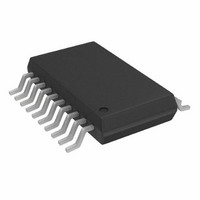
IC VGA SINGLE W/PREAMP 20-SSOP
Manufacturer
Analog Devices Inc
Series
X-AMP®r
Type
Variable Gain Amplifierr
Datasheet
1.AD8331ARQZ.pdf
(56 pages)
Specifications of AD8331ARQ-REEL
Rohs Status
RoHS non-compliant
Design Resources
Interfacing the High Frequency AD8331 to AD9215 (CN0096)
Applications
Signal Processing
Mounting Type
Surface Mount
Package / Case
20-QSOP
For Use With
AD8331-EVALZ - BOARD EVAL FOR AD8331


AD8331 EVALUATION BOARD
GENERAL DESCRIPTION
The
evaluating the AD8331 variable gain amplifier (VGA). The
board is provided completely assembled and tested; the user
simply connects an input signal, VGAIN sources, and a 5 V
power supply. The AD8331-EVALZ is lead free and RoHS
compliant. Figure 95 is a photograph of the board.
USER-SUPPLIED OPTIONAL COMPONENTS
As shown in the schematic in Figure 96, the board provides for
optional components. The components shown in black are for
typical operation, and the components shown in gray are
installed at the user’s discretion.
As shipped, the LNA input impedance of the AD8331-EVALZ is
configured for 50 Ω to accommodate most signal generators and
network analyzers. Input impedances up to 6 kΩ are realized by
changing the values of RFB and CSH. Refer to the Theory of
Operation section for details on this circuit feature. See Table 9
for typical values of input impedance and corresponding
components.
Table 9. LNA External Component Values for Common
Source Impedances
R
50
75
100
200
500
6 k
The board is designed for 0603 size, surface-mount components.
Back-to-back diodes can be installed at Location D3 if desired.
To evaluate the LNA as a standalone amplifier, install optional
SMA connectors LON and LOP and capacitors C1 and C2;
typical values are 0.1 μF or smaller. At R4 and R8, 0 Ω resistors
are installed unless capacitive loads larger than 10 pF are connected
to the SMA connectors LON and LOP (such as coaxial cables).
In that event, small value resistors (68 Ω to 100 Ω) must be
installed at R4 and R8 to preserve the stability of the amplifier.
A resistor can be inserted at RCLMP if output clamping is
desired. Refer to Table 8 for appropriate values.
IN
(Ω)
AD8331
evaluation board is a platform for testing and
RFB (Ω, Nearest 1% Value)
274
412
562
1.13 k
3.01 k
∞
CSH (pF)
22
12
8
1.2
None
None
Rev. G | Page 39 of 56
MEASUREMENT SETUP
The basic board connection for measuring bandwidth is shown
in Figure 97. A 5 V, 100 mA minimum power supply and a low
noise, voltage reference supply for GAIN are required. Table 10
lists jumpers, and Figure 97 shows their functions and positions.
The preferred signal detection method is a differential probe
connected to VO, as shown in Figure 97. Single-ended loads can be
connected using the board edge SMA connector, VOH. Be sure to
take into account the 25.8 dB attenuation incurred when using the
board in this manner. For connection to an ADC, the 270 Ω series
resistors can be replaced with 0 Ω or other appropriate values.
Table 10. Jumper Functions
Switch
LNA_EN
VGA_EN
W5, W6
GN_SLOPE
GN_HI_LO
BOARD LAYOUT
The evaluation board circuitry uses four conductor layers. The
two inner layers are grounded, and all interconnecting circuitry
is located on the outer layers. Figure 99 to Figure 102 illustrate
the copper patterns.
Function
Enables the LNA when in the top position
Enables the VGA when in the top position
Connects the AD8331 outputs to the SMA connectors
Left = gain increases with V
Right = gain decreases with V
Left = high gain
Right = LO gain
Figure 95. Photograph of AD8331-EVALZ
AD8331/AD8332/AD8334
GAIN
GAIN
Related parts for AD8331ARQ-REEL
Image
Part Number
Description
Manufacturer
Datasheet
Request
R

Part Number:
Description:
IC VGA SINGLE W/PREAMP 20-SSOP
Manufacturer:
Analog Devices Inc
Datasheet:
Part Number:
Description:
Single VGA
Manufacturer:
Analog Devices Inc
Datasheet:

Part Number:
Description:
BOARD EVAL FOR AD8331
Manufacturer:
Analog Devices Inc
Datasheet:

Part Number:
Description:
BOARD EVAL FOR AD8331
Manufacturer:
Analog Devices Inc
Datasheet:

Part Number:
Description:
Ultralow Noise VGAs with Preamplifier and Programmable RIN
Manufacturer:
Analog Devices
Datasheet:

Part Number:
Description:
±1.7g Dual-Axis IMEMS Accelerometer Evaluation Board
Manufacturer:
Analog Devices Inc
Datasheet:

Part Number:
Description:
Inertial Sensor Evaluation System
Manufacturer:
Analog Devices Inc
Datasheet:
Part Number:
Description:
Manufacturer:
Analog Devices Inc
Datasheet:
Part Number:
Description:
Manufacturer:
Analog Devices Inc
Datasheet:
Part Number:
Description:
Manufacturer:
Analog Devices Inc
Datasheet:
Part Number:
Description:
Manufacturer:
Analog Devices Inc
Datasheet:
Part Number:
Description:
Manufacturer:
Analog Devices Inc
Datasheet:
Part Number:
Description:
Manufacturer:
Analog Devices Inc
Datasheet: