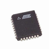
AT49LW080-33JC SL383 Atmel, AT49LW080-33JC SL383 Datasheet - Page 15

AT49LW080-33JC SL383
Manufacturer Part Number
AT49LW080-33JC SL383
Description
IC FLASH 8MBIT 33MHZ 32PLCC
Manufacturer
Atmel
Datasheet
1.AT49LW080-33JC.pdf
(34 pages)
Specifications of AT49LW080-33JC SL383
Format - Memory
FLASH
Memory Type
FLASH
Memory Size
8M (1M x 8)
Speed
33MHz
Interface
Parallel
Voltage - Supply
3 V ~ 3.6 V
Operating Temperature
0°C ~ 85°C
Package / Case
32-PLCC
Lead Free Status / RoHS Status
Contains lead / RoHS non-compliant
Table 6-7.
Note:
6.8
6.9
1966G–FLASH–3/05
Data
00
01
02
03
04
05
06
07
1. The Write Lock bit must be set to the desired protection state prior to starting a program or erase operation since it is sam-
Read Lock
Write Lock
pled at the beginning of the operation. Changing the state of the Write Lock bit during a program or erase operation may
cause unpredictable results. If the state of the Write Lock bit changes during a program suspend or erase suspend state, the
changes to the sector’s locking status do not take place immediately. The suspended operation may be resumed success-
fully. The new lock status will take place after the program or erase operation completes. The individual bit functions are
described in the following sections.
Register-based Locking Value Definitions
Reserved
Data 7 - 3
00000
00000
00000
00000
00000
00000
00000
00000
The default read status of all sectors upon power-up is read-unlocked. When a sector’s read-
lock bit is set (1 state), data cannot be read from that sector. An attempted read from a
read-locked sector will result in data 00H being read. (Note that failure is not reflected in the sta-
tus register). The read-lock status can be unlocked by clearing (0 state) the read-lock bit,
provided the lock-down bit has not been set. The current read-lock status of a particular sector
can be determined by reading the corresponding read-lock bit.
The default write status of all sectors upon power-up is write-locked (1 state). Any program or
erase operations attempted on a locked sector will return an error in the status register (indicat-
ing sector lock). The status of the locked sector can be changed to unlocked (0 state) by clearing
the write-lock bit, provided the lock-down bit is not also set. The current write-lock status of a
particular sector can be determined by reading the corresponding write-lock bit. Any program or
erase operations attempted on a locked sector will return an error in the status register (indicat-
ing sector lock). The write-lock functions in conjunction with the hardware write-lock pins, TBL
and WP. When active, these pins take precedence over the register-locking function and write-
lock the top sector or remaining sectors, respectively. Reading this register will not read the state
of the TBL or WP pins.
Read Lock,
Data 2
0
0
0
0
1
1
1
1
Lock-down,
Data 1
0
0
1
1
0
0
1
1
Write Lock,
Data 0
0
1
0
1
0
1
0
1
Resulting Sector State
Full access
Write locked. Default state at power-up
Locked open (full access locked down)
Write locked down
Read locked
Read and write locked
Read locked down
Read and write locked down
(1)
AT49LW080
15


