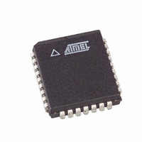
AT49LW080-33JC SL383 Atmel, AT49LW080-33JC SL383 Datasheet - Page 22

AT49LW080-33JC SL383
Manufacturer Part Number
AT49LW080-33JC SL383
Description
IC FLASH 8MBIT 33MHZ 32PLCC
Manufacturer
Atmel
Datasheet
1.AT49LW080-33JC.pdf
(34 pages)
Specifications of AT49LW080-33JC SL383
Format - Memory
FLASH
Memory Type
FLASH
Memory Size
8M (1M x 8)
Speed
33MHz
Interface
Parallel
Voltage - Supply
3 V ~ 3.6 V
Operating Temperature
0°C ~ 85°C
Package / Case
32-PLCC
Lead Free Status / RoHS Status
Contains lead / RoHS non-compliant
9. Absolute Maximum Ratings*
Notes:
10. Operating Conditions
Temperature and V
Note:
11. FWH Interface DC Input/Output Specifications
Notes:
22
Voltage on Any Pin
(except V
V
Symbol
T
V
Symbol
V
V
V
V
I
V
V
C
C
L
IL
pin(2)
C
OH
OL
PP
CC
IH
IH
IL
IL
IN
CLK
(4)
(3)
(3)
(INIT)
(INIT)
Voltage ............................................ -0.5V to +13.0V
1. All specified voltages are with respect to GND. Minimum DC voltage on the V
2. Maximum DC voltage on V
3. Connection to supply of V
4. Do not violate processor or chipset limitations on the INIT pin.
1. This temperature requirement is different from the normal commercial operating condition of Flash memories.
1. Input leakage currents include high-Z output leakage for all bi-directional buffers with tri-state outputs.
2. Refer to PCI spec.
3. Inputs are not “5-volt safe.”
4. I
5. Do not violate processor or chipset specifications regarding the INIT pin voltage.
(5)
PP
(5)
AT49LW080
undershoot to -2.0V for periods of <20 ns. During transitions, this level may overshoot to V
) .................................-0.5V to +VCC + 0.5V
IL
may be changed on IC and ID pins (up to 200 µA) if pulled against internal pull-downs. Refer to the pin descriptions
Parameter
Operating Temperature
V
Parameter
Input High Voltage
INIT Input High Voltage
INIT Input Low Voltage
Input Low Voltage
Input Leakage Current
Output High Voltage
Output Low Voltage
Input Pin Capacitance
CLK Pin Capacitance
Recommended Pin Inductance
CC
CC
Supply Voltage (3.3V ± 0.3V)
HH
PP
is allowed for a maximum cumulative period of 80 hours.
(1)
may overshoot to +13.0V for periods <20 ns.
(1)
(1)(2)(4)
(1)(2)(3)
Test Condition
Case Temperature
Conditions
0 < V
I
I
OUT
OUT
= -500 µA
= 1500 µA
IN
*NOTICE:
< V
CC
Stresses beyond those listed under “Absolute
Maximum Ratings” may cause permanent dam-
age to the device. This is a stress rating only and
functional operation of the device at these or any
other conditions beyond those indicated in the
operational sections of this specification is not
implied. Exposure to absolute maximum rating
conditions for extended periods may affect device
reliability.
PP
pin is -0.5V. During transitions, this level may
Min
3.0
0
0.5 V
0.9 V
1.35
Min
-0.5
3
CC
CC
CC
+ 2.0V for periods <20 ns.
V
V
Max
+85
0.3 V
0.1 V
3.6
CC
CC
Max
0.85
±10
13
12
20
+ 0.5
+ 0.5
CC
CC
1966G–FLASH–3/05
Unit
Units
°C
V
µA
nH
pF
pF
V
V
V
V
V
V


