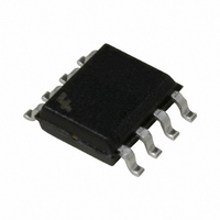
FAN103MY Fairchild Semiconductor, FAN103MY Datasheet

FAN103MY
Specifications of FAN103MY
Available stocks
Related parts for FAN103MY
FAN103MY Summary of contents
Page 1
... PDA, digital cameras, power tools, etc. Replaces linear transformer and RCC SMPS Ordering Information Part Number Operating Temperature Range -40°C to +105°C FAN103MY © 2010 Fairchild Semiconductor Corporation FAN103 • Rev. 1.0.4 Description This third-generation Primary-Side-Regulation (PSR) and highly integrated PWM controller provides several ...
Page 2
... Application Diagram Input Internal Block Diagram © 2010 Fairchild Semiconductor Corporation FAN103 • Rev. 1.0 sn2 sn1 VDD VDD VS 5 GATE N.C 7 GATE COMR 6 GND Figure 2. Typical Application Figure 3. Functional Block Diagram sn2 MOSFET R SENSE DC R Output d www.fairchildsemi.com ...
Page 3
... GND Ground Connect High Voltage. This pin connects to bulk capacitor for high-voltage startup © 2010 Fairchild Semiconductor Corporation FAN103 • Rev. 1.0.4 F: Fairchild Logo Z: Plant Code X: 1-Digit Year Code Y: 1-Digit Week Code TT: 2-Digit Die-Run Code T: Package Type (M=SOP) P: Y=Green Package M: Manufacture Flow Code Figure 4 ...
Page 4
... Fairchild does not recommend exceeding them or designing to Absolute Maximum Ratings. Symbol T Operating Ambient Temperature A © 2010 Fairchild Semiconductor Corporation FAN103 • Rev. 1.0.4 Parameter (1)(2) <50°C) A Human Body Model (Except HV Pin), ...
Page 5
... Propagation Delay to GATE Output PD t Minimum On Time at No-Load MIN-N V Threshold Voltage for Current Limit TH Threshold Voltage on VS Pin Smaller than V TL 0.5V © 2010 Fairchild Semiconductor Corporation FAN103 • Rev. 1.0.4 =15V and T =25°C. A Conditions OVP DD V =100V DC HV=500V, V +1V ...
Page 6
... CLAMP Over-Temperature-Protection Section T Threshold Temperature for OTP OTP Note: 3. When the over-temperature protection is activated, the power system enters latch mode and output is disabled. © 2010 Fairchild Semiconductor Corporation FAN103 • Rev. 1.0.4 (Continued) =15V and T =25°C. A Conditions V =20V, Gate Sinks 10mA ...
Page 7
... Temperature (ºC) Figure 8. Operating Current (I 2.525 2.515 2.505 2.495 2.485 2.475 -40 -30 - Temperature (ºC) Figure 10. Reference Voltage (V © 2010 Fairchild Semiconductor Corporation FAN103 • Rev. 1.0.4 5.5 5.3 5.1 4.9 4.7 4 100 125 -40 ) Figure 7. DD- -40 50 ...
Page 8
... Temperature (ºC) Figure 14. Supply Current Drawn from Pin HV (I vs. Temperature 2.7 2.62 2.54 2.46 2.38 2.3 -40 -30 - Temperature (ºC) Figure 16. Green Mode Starting Voltage on EA_V (V © 2010 Fairchild Semiconductor Corporation FAN103 • Rev. 1.0 100 125 -40 Figure 13. Minimum Frequency at CCM (f 1100 ...
Page 9
... Typical Performance Characteristics Figure 19. Output Clamp Voltage (V Figure 20. Variation Test Voltage on COMR Pin for Cable Compensation (V © 2010 Fairchild Semiconductor Corporation FAN103 • Rev. 1.0.4 12 11.2 10.4 9.6 8.8 8 -40 -30 - Temperature (ºC) Figure 18. IC Bias Current (I ) vs. Temperature tc 1.6 1.5 1.4 1 ...
Page 10
... Therefore, during constant voltage regulation mode, V duty cycle while V is saturated to HIGH. During COMI constant current regulation mode, V duty cycle while V is saturated to HIGH. COMV © 2010 Fairchild Semiconductor Corporation FAN103 • Rev. 1.0.4 discontinuous input voltage ( Gate ) ...
Page 11
... EMI test equipment. FAN103 has an internal frequency hopping circuit that changes the switching frequency between 47kHz and 53kHz with a period, as shown in Figure 24. © 2010 Fairchild Semiconductor Corporation FAN103 • Rev. 1.0.4 Figure 25. Frequency Hopping High-Voltage Startup Figure 25 shows the HV-startup circuit for FAN103 applications ...
Page 12
... OVP is triggered and the PWM switching is disabled. The OVP has a de-bounce time (typically 200µs) to prevent false triggering due to switching noises. © 2010 Fairchild Semiconductor Corporation FAN103 • Rev. 1.0.4 Over-Temperature Protection (OTP) The built-in temperature-sensing circuit shuts down PWM output if the junction temperature exceeds 140° ...
Page 13
... High efficiency (>68.17% at Full Load) Meeting EPS 2.0 Regulation with Enough Margin Low standby (Pin <30mW at No Load Condition) Tight output regulation (CV: ±5%, CC: ±7%) 74.00% 72.00% 70.00% 68.00% 66.00% 64.00% 62.00% 0.250 0.500 Figure 28. Measured Efficiency and Output Regulation © 2010 Fairchild Semiconductor Corporation FAN103 • Rev. 1.0.4 Input Voltage Range 90~265V ...
Page 14
... When W2 is winding, put 1 layer tape after wind first layer. TERMINAL W4R 7 9 Primary-Side Inductance Primary-Side Effective Leakage © 2010 Fairchild Semiconductor Corporation FAN103 • Rev. 1.0.4 (Continued) Figure 30. Bobbin Winding Diagram WIRE Ts 2UEW 0.23 2UEW 0.17 COPPER SHIELD 1.2 TEX-E 0.6*1 9 CORE ROUNDING TAPE Pin Specification 1- ...
Page 15
... Package drawings are provided as a service to customers considering Fairchild components. Drawings may change in any manner without notice. Please note the revision and/or date on the drawing and contact a Fairchild Semiconductor representative to verify or obtain the most recent revision. Package specifications do not expand the terms of Fairchild’s worldwide terms and conditions, specifically the warranty therein, which covers Fairchild products. Always visit Fairchild Semiconductor’ ...
Page 16
... Fairchild Semiconductor Corporation FAN103 • Rev. 1.0.4 16 www.fairchildsemi.com ...


