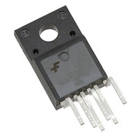
FSQ0765RQUDTU Fairchild Semiconductor, FSQ0765RQUDTU Datasheet - Page 16

FSQ0765RQUDTU
Manufacturer Part Number
FSQ0765RQUDTU
Description
IC CONV QUASI-RES 650V TO-220F-6
Manufacturer
Fairchild Semiconductor
Series
FPS™r
Datasheet
1.FSQ0765RQWDTU.pdf
(19 pages)
Specifications of FSQ0765RQUDTU
Output Isolation
Isolated
Frequency Range
48kHz ~ 67kHz
Voltage - Input
9 V ~ 20 V
Voltage - Output
650V
Power (watts)
90W
Operating Temperature
-25°C ~ 85°C
Package / Case
TO-220-6 Formed Leads
On Resistance (max)
1.3 Ohms
Maximum Operating Temperature
+ 85 C
Minimum Operating Temperature
+ 25 C
Maximum Power Dissipation
45 W
Mounting Style
Through Hole
Off Time (max)
63 ns
On Time (max)
27 ns
Operating Frequency
66.7 KHz
Propagation Delay Time
200 ns
Supply Current
3 mA
Supply Voltage (max)
20 V
Lead Free Status / RoHS Status
Lead free / RoHS Compliant
Available stocks
Company
Part Number
Manufacturer
Quantity
Price
Company:
Part Number:
FSQ0765RQUDTU
Manufacturer:
Fairchi/ON
Quantity:
30 000
FSQ0765RQ Rev. 1.0.1
© 2008 Fairchild Semiconductor Corporation
If no valley is found during t
forced to turn on at the end of t
the devices have a minimum switching frequency of
48kHz and a maximum switching frequency of 67kHz.
Figure 34. QRC Operation with Limited Frequency
One-shot
GateX2
FSQ0765R Rev. 00
V
AVS
V
gate
DS
I
DS
t
B
GateX2: Counting V
=15
t
I
triggering
B
DS
I
DS
=15
t
fixed
B
=15
μ
I
DS
s
μ
t
s
s
max
t
B
t
μ
s
t
B
max
s
=21
=15
1st or 2nd is depend on GateX2
t
t
t
s
s
s
=21
μ
μ
gate
s
s
μ
every 2 pulses independent on other signals .
s
W
, the internal SenseFET is
V
W
I
gate
DS
fixed
Figure 36. Alternating Valley Switching (AVS)
I
(Case D). Therefore,
continued 2 pulses
DS
I
DS
1st valley switching
t
I
W
DS
FSQ0765R Rev. 00
=6
de-triggering
μ
t
s
B
D
A
B
C
fixed
triggering
V
gate
continued another 2 pulses
t
B
16
2nd valley switching
8. AVS (Alternating Valley Switching): Due to the
quasi-resonant operation with limited frequency, the
switching frequency varies depending on input voltage,
load transition, and so on. At high input voltage, the
switching on time is relatively small compared to low
input voltage. The input voltage variance is small and the
switching frequency modulation width becomes small. To
improve the EMI performance, AVS is enabled when
input voltage is high and the switching on time is small.
Internally, quasi-resonant operation is divided into two
categories; one is first-valley switching and the other is
second-valley switching after blanking time. In AVS, two
successive occurrences of first-valley switching and the
other two successive occurrences of second-valley
switching is alternatively selected to maximize frequency
modulation. As depicted in Figure 35, the switching
frequency hops when the input voltage is high. The
internal timing diagram of AVS is described in Figure 36.
67kHz
59kHz
53kHz
48kHz
f
s
frequency
fixed
Constant
FSQ0765R Rev.00
CCM
Figure 35. Switching Frequency Range
Modulation frequency is approximately 17kHz.
D
1st valley- 2nd valley frequency modulation.
t
B
1st or 2nd is dependent on GateX2
Assume the resonant period is 2us
C
Variable frequency within limited range
fixed
AVS trigger point
1st valley switching
B
t
B
DCM
V
gate
fixed
continued 2 pulses
AVS region
A
t
B
www.fairchildsemi.com
17
19
21
V
15
1
1
μ
1
μ
μ
in
1
s
μ
s
s
s


