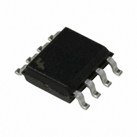
FAN7382MX Fairchild Semiconductor, FAN7382MX Datasheet - Page 4

FAN7382MX
Manufacturer Part Number
FAN7382MX
Description
IC DRIVER GATE HALF BRIDGE 8SOIC
Manufacturer
Fairchild Semiconductor
Type
High Side/Low Sider
Datasheet
1.FAN7382M1X.pdf
(15 pages)
Specifications of FAN7382MX
Configuration
Half Bridge
Input Type
Non-Inverting
Delay Time
170ns
Current - Peak
350mA
Number Of Configurations
1
Number Of Outputs
2
High Side Voltage - Max (bootstrap)
600V
Voltage - Supply
10 V ~ 20 V
Operating Temperature
-40°C ~ 125°C
Mounting Type
Surface Mount
Package / Case
8-SOIC (3.9mm Width)
Rise Time
140 ns
Fall Time
80 ns
Supply Voltage (min)
10 V
Supply Current
0.6 mA
Maximum Power Dissipation
0.625 W
Maximum Operating Temperature
+ 125 C
Mounting Style
SMD/SMT
Bridge Type
Half Bridge
Minimum Operating Temperature
- 40 C
Number Of Drivers
2
Lead Free Status / RoHS Status
Lead free / RoHS Compliant
Other names
FAN7382MXTR
FAN7382MX_NL
FAN7382MX_NLTR
FAN7382MX_NLTR
FAN7382MX_NL
FAN7382MX_NLTR
FAN7382MX_NLTR
Available stocks
Company
Part Number
Manufacturer
Quantity
Price
Company:
Part Number:
FAN7382MX
Manufacturer:
Fairchild Semiconductor
Quantity:
43 250
Company:
Part Number:
FAN7382MX
Manufacturer:
ST
Quantity:
21 000
Part Number:
FAN7382MX
Manufacturer:
FAIRCHILD/仙童
Quantity:
20 000
FAN7382 Rev. 1.0.8
© 2005 Fairchild Semiconductor Corporation
Absolute Maximum Ratings
Stresses exceeding the absolute maximum ratings may damage the device. The device may not function or be opera-
ble above the recommended operating conditions and stressing the parts to these levels is not recommended. In addi-
tion, extended exposure to stresses above the recommended operating conditions may affect device reliability. The
absolute maximum ratings are stress ratings only.
Notes:
2. Mounted on 76.2 x 114.3 x 1.6mm PCB (FR-4 glass epoxy material).
3. Refer to the following standards:
4. Do not exceed P
Recommended Operating Ratings
The Recommended Operating Conditions table defines the conditions for actual device operation. Recommended
operating conditions are specified to ensure optimal performance to the datasheet specifications. Fairchild does not
recommend exceeding them or designing to Absolute Maximum Ratings.
Symbol
JESD51-2: Integral circuits thermal test method environmental conditions - natural convection
JESD51-3: Low effective thermal conductivity test board for leaded surface mount packages
P
Symbol
dV
D
V
V
V
COM
T
V
V
V
V
V
V
(2)(3)(4)
T
V
θ
V
V
HO
LO
CC
T
STG
IN
HO
A
CC
S
JA
B
S
LO
IN
S
B
J
/dt
High-side floating supply voltage
High-side floating supply offset voltage
High-side (HO) output voltage
Low-side (LO) output voltage
Logic input voltage (HIN, LIN)
Low-side supply voltage
Ambient temperature
High-side offset voltage
High-side floating supply voltage
High-side floating output voltage HO
Low-side and logic fixed supply voltage
Low-side output voltage LO
Logic input voltage (HIN, LIN)
Logic ground
Allowable offset voltage slew rate
Power dissipation
Thermal resistance, junction-to-ambient
Junction temperature
Storage temperature
D
under any circumstances.
Characteristics
Parameter
4
14-SOP
14-SOP
V
8-SOP
8-SOP
V
V
8-DIP
8-DIP
Min.
CC
-0.3
-0.3
-0.3
-0.3
S
B
V
6-V
-0.3
COM
COM
Min.
-25
-25
S
-40
V
10
+10
S
CC
V
V
V
V
V
Max.
0.625
CC
CC
CC
B
B
V
625
200
110
100
150
150
Max.
1.0
1.2
25
50
V
+0.3
+0.3
V
600
125
S
+0.3
+0.3
+0.3
V
20
+20
CC
CC
B
www.fairchildsemi.com
°C/W
Unit
V/ns
Unit
°C
°C
W
°C
V
V


